RM0367 Rev 7 705/1043
RM0367 Inter-integrated circuit (I2C) interface
763
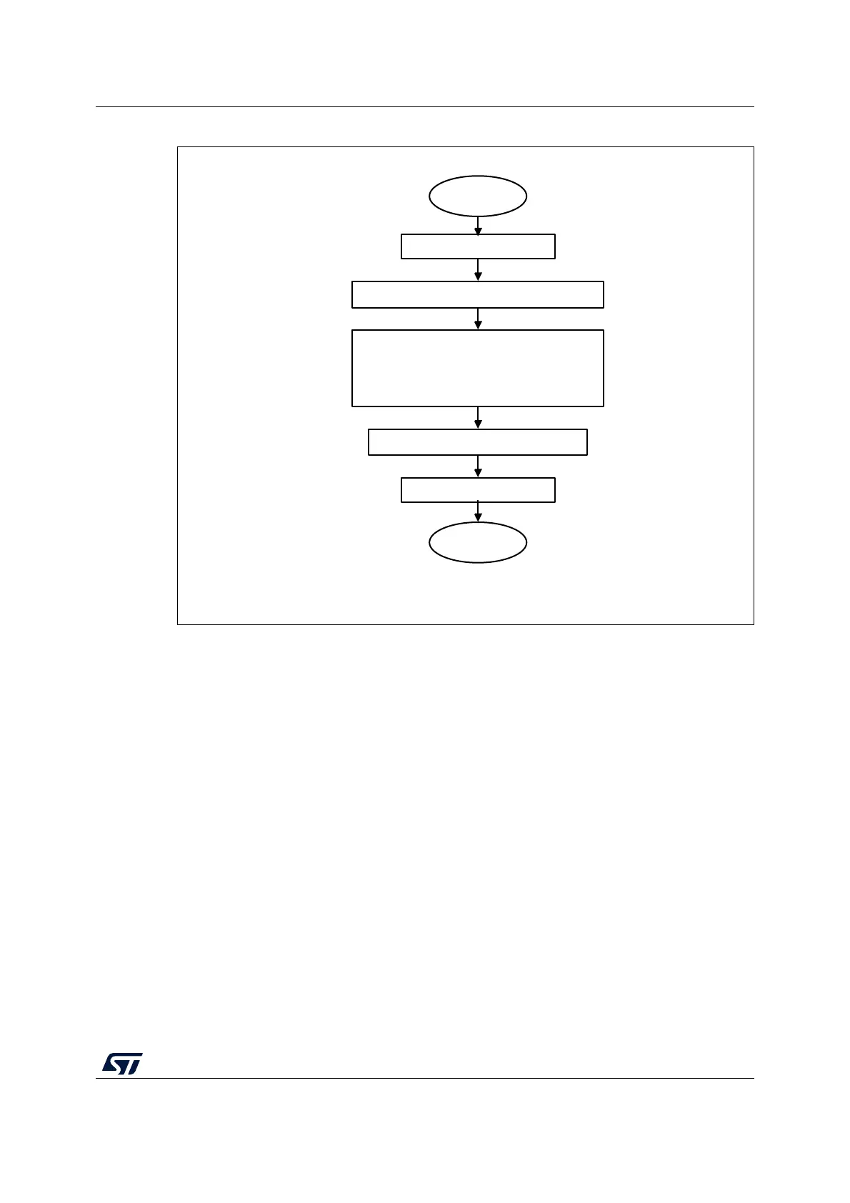
Figure 215. I2C initialization flowchart
28.4.7 Software reset
A software reset can be performed by clearing the PE bit in the I2C_CR1 register. In that
case I2C lines SCL and SDA are released. Internal states machines are reset and
communication control bits, as well as status bits come back to their reset value. The
configuration registers are not impacted.
Here is the list of impacted register bits:
1. I2C_CR2 register: START, STOP, NACK
2. I2C_ISR register: BUSY, TXE, TXIS, RXNE, ADDR, NACKF, TCR, TC, STOPF, BERR,
ARLO, OVR
and in addition when the SMBus feature is supported:
1. I2C_CR2 register: PECBYTE
2. I2C_ISR register: PECERR, TIMEOUT, ALERT
PE must be kept low during at least 3 APB clock cycles in order to perform the software
reset. This is ensured by writing the following software sequence: - Write PE=0 - Check
PE=0 - Write PE=1.
MS19847V2
Clear PE bit in I2C_CR1
Initial settings
Configure ANFOFF and DNF[3:0] in I2C_CR1
Configure PRESC[3:0],
SDADEL[3:0], SCLDEL[3:0], SCLH[7:0],
SCLL[7:0] in I2C_TIMINGR
Configure NOSTRETCH in I2C_CR1
Set PE bit in I2C_CR1
End