Low-power universal asynchronous receiver transmitter (LPUART) RM0367
834/1043 RM0367 Rev 7
The following pins are required in RS232 Hardware flow control mode:
• CTS: Clear To Send blocks the data transmission at the end of the current transfer
when high
• RTS: Request to send indicates that the LPUART is ready to receive data (when low).
The following pin is required in RS485 Hardware control mode:
• DE: Driver Enable activates the transmission mode of the external transceiver.
Note: DE and RTS share the same pin.
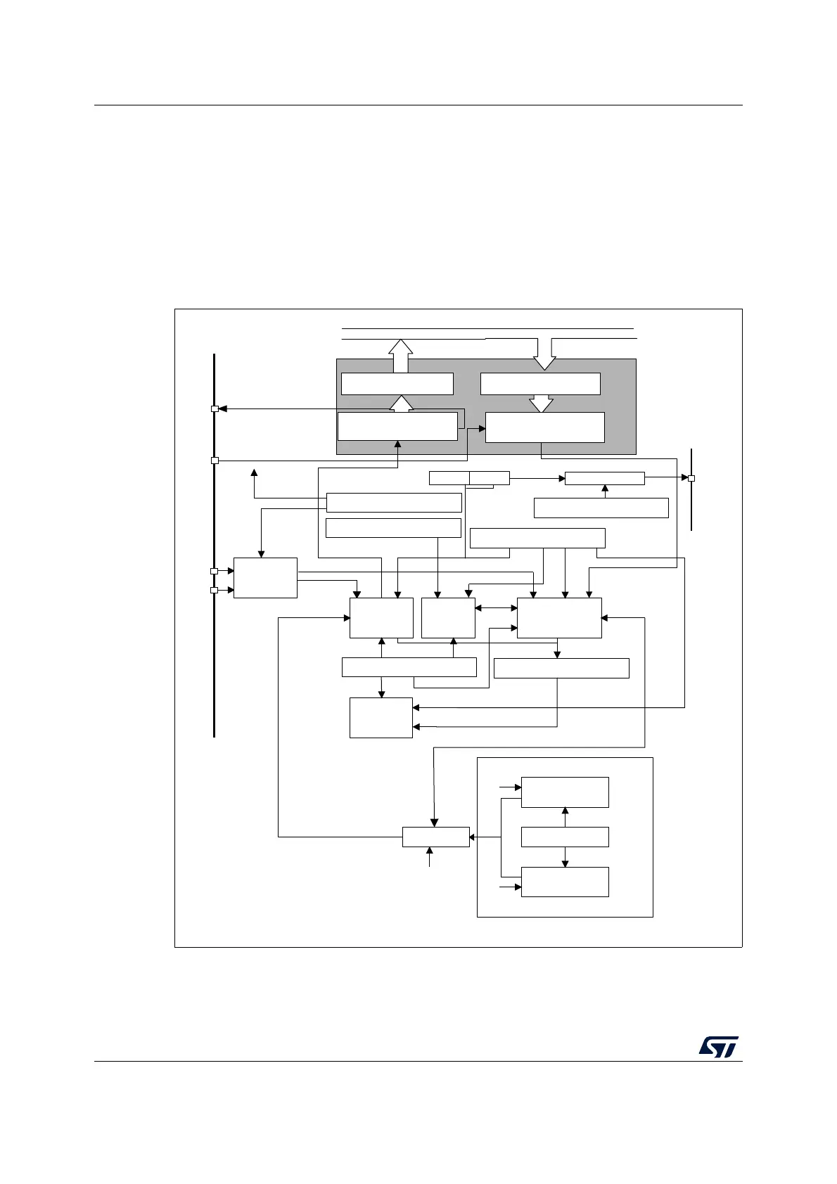
Figure 267. LPUART block diagram
MSv31884V6
BRR[19:0]
T
Write
Read
DR (data register)
(CPU or DMA) (CPU or DMA)
PRDATA PWDATA
LPUARTx_CR3 register
LPUARTx_CR2 register
RTS/
DE
CTS
Hardware
flow
controller
Transmit
control
LPUARTx_CR1 register
Wakeup
unit
LPUARTx_CR1 register
LPUART_GTPR register
GT PSC
CK control
LPUARTx_CR2 register
Receiver
control
Receiver
clock
LPUARTx_ISR register
LPUART
interrupt
control
LPUARTx_BRR register
Transmitter
rate controller
Receiver rate
controller
/LPUARTDIV
f
CK
(
f
LSE
,
f
HSI
,
f
PCLK
or f
SYS
)
Transmitter
clock
Conventional baud rate generator
CK
LPUARTDIV = BBR[19:0]
Receive shift register
R
TX
RX
Transmit shift register
Transmit data register
(TDR)
Receive data register
(RDR)