Universal synchronous/asynchronous receiver transmitter (USART/UART) RM0367
804/1043 RM0367 Rev 7
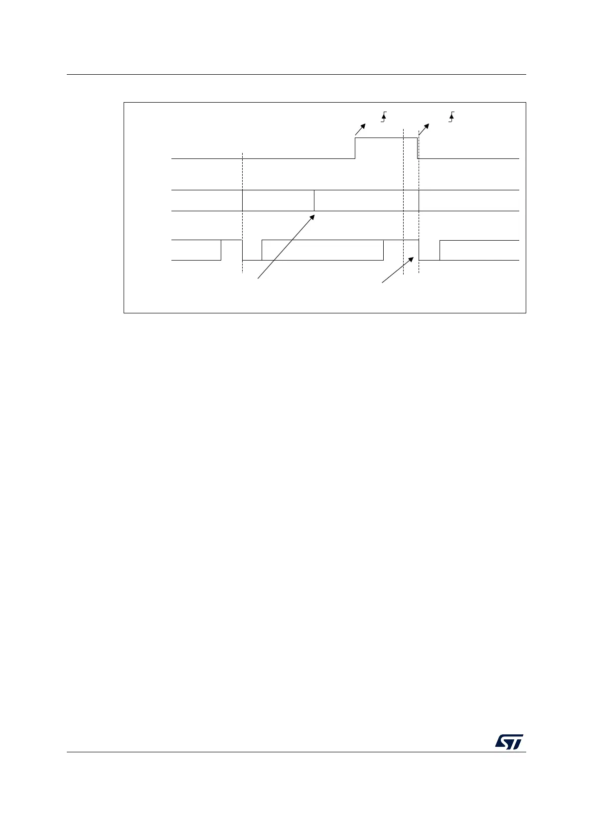
Figure 265. RS232 CTS flow control
Note: For correct behavior, CTS must be asserted at least 3 USART clock source periods before
the end of the current character. In addition it should be noted that the CTSCF flag may not
be set for pulses shorter than 2 x PCLK periods.
For code example, refer to A.17.12: USART hardware flow control code example.
RS485 Driver Enable
The driver enable feature is enabled by setting bit DEM in the USART_CR3 control register.
This allows the user to activate the external transceiver control, through the DE (Driver
Enable) signal. The assertion time is the time between the activation of the DE signal and
the beginning of the START bit. It is programmed using the DEAT [4:0] bit fields in the
USART_CR1 control register. The de-assertion time is the time between the end of the last
stop bit, in a transmitted message, and the de-activation of the DE signal. It is programmed
using the DEDT [4:0] bit fields in the USART_CR1 control register. The polarity of the DE
signal can be configured using the DEP bit in the USART_CR3 control register.
In USART, the DEAT and DEDT are expressed in sample time units (1/8 or 1/16 bit duration,
depending on the oversampling rate).
29.5.17 Wakeup from Stop mode using USART
The USART is able to wake up the MCU from Stopmode when the UESM bit is set and the
USART clock is set to HSI or LSE (refer to Section Reset and clock control (RCC)).
• USART source clock is HSI
If during Stop mode the HSI clock is switched OFF, when a falling edge on the USART
receive line is detected, the USART interface requests the HSI clock to be switched
ON. The HSI clock is then used for the frame reception.
– If the wakeup event is verified, the MCU wakes up from low-power mode and data
reception goes on normally.
– If the wakeup event is not verified, the HSI clock is switched OFF again, the MCU
is not waken up and stays in low-power mode and the clock request is released.
MSv31167V2
Start
bit
Stop
bit
TX
TDR
CTS
Data 1
Data 2
Stop
bit
Idle
Start
bit
Data 2 Data 3
Data 3
empty empty
CTS
CTS
Transmit data register
Writing data 3 in TDR
Transmission of Data 3 is
delayed until CTS = 0