RM0367 Rev 7 791/1043
RM0367 Universal synchronous/asynchronous receiver transmitter (USART/UART)
872
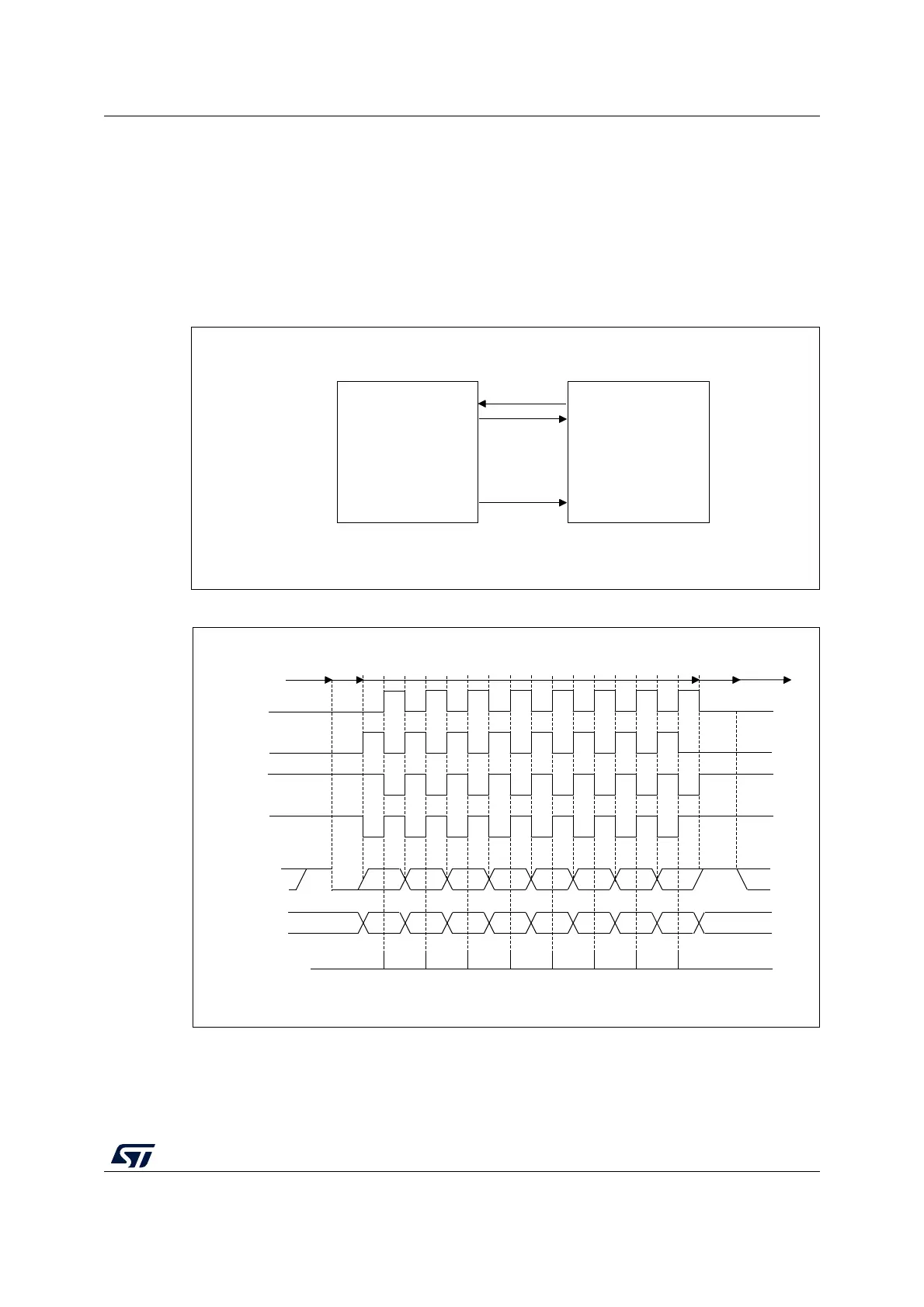
Note: The CK pin works in conjunction with the TX pin. Thus, the clock is provided only if the
transmitter is enabled (TE=1) and data is being transmitted (the data register USART_TDR
written). This means that it is not possible to receive synchronous data without transmitting
data.
The LBCL, CPOL and CPHA bits have to be selected when the USART is disabled (UE=0)
to ensure that the clock pulses function correctly.
For code example, refer to A.17.6: USART LIN mode code example.
Figure 253. USART example of synchronous transmission
Figure 254. USART data clock timing diagram (M bits = 00)
MSv31158V2
USART
Synchronous device
(e.g. slave SPI)
RX
TX
Data out
Data in
Clock
CK
MSv34709V2
0 1 2 3 4 5 6 7
0 1 2 3 4 5 6 7
*
*
*
*
MSB
MSB
LSB
LSB
Start
Start Stop
Idle or preceding
transmission
Idle or next
transmission
*
*LBCL bit controls last data pulse
Capture strobe
Data on RX
(from slave)
Data on TX
(from master)
Clock (CPOL=1, CPHA=1)
Clock (CPOL=1, CPHA=0)
Clock (CPOL=0, CPHA=1)
Clock (CPOL=0, CPHA=0)
Stop
M bits = 00 (8 data bits)