Analog-to-digital converter (ADC) RM0367
326/1043 RM0367 Rev 7
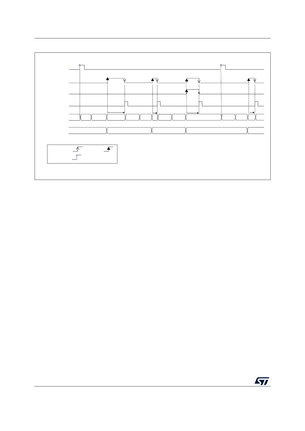
Figure 48. Behavior with WAIT = 1, AUTOFF = 1
1. EXTSEL = TRGx, EXTEN = 01 (rising edge), CONT = x, ADSTART = 1, CHSEL = 0xF, SCANDIR = 0, WAIT = 1,
AUTOFF = 1
For code example, refer to A.8.13: Auto off and wait mode sequence code example.
14.7 Analog window watchdog (AWDEN, AWDSGL, AWDCH,
ADC_TR)
14.7.1 Description of the analog watchdog
The AWD analog watchdog is enabled by setting the AWDEN bit in the ADC_CFGR1
register. It is used to monitor that either one selected channel or all enabled channels
(see
Table 65: Analog watchdog channel selection)
remain within a configured voltage range
(window) as shown in Figure 49.
The AWD analog watchdog status bit is set if the analog voltage converted by the ADC is
below a lower threshold or above a higher threshold. These thresholds are programmed in
HT[11:0] and LT[11:0] bit of ADC_TR register. An interrupt can be enabled by setting the
AWDIE bit in the ADC_IER register.
The AWD flag is cleared by software by programming it to it.
When converting data with a resolution of less than 12-bit (according to bits RES[1:0]), the
LSB of the programmed thresholds must be kept cleared because the internal comparison
is always performed on the full 12-bit raw converted data (left aligned).
For code example, refer to A.8.14: Analog watchdog code example.
Table 64 describes how the comparison is performed for all the possible resolutions.
MSv30346V2
D1 D2 D3 D4
TRGx
EOC
EOS
ADC_DR Read
access
ADC state
ADC_DR
RDY CH1 OFFStartup
CH2
OFF
Startup
DLY
Startup CH3
OFF
DLY
DLY
Startup CH1
OFF
CH2
DLY
by H/Wby S/W
triggered