RM0367 Rev 7 893/1043
RM0367 Serial peripheral interface/ inter-IC sound (SPI/I2S)
922
Note: To detect TI frame errors in slave transmitter only mode by using the Error interrupt
(ERRIE=1), the SPI must be configured in 2-line unidirectional mode by setting BIDIMODE
and BIDIOE to 1 in the SPI_CR1 register. When BIDIMODE is set to 0, OVR is set to 1
because the data register is never read and error interrupts are always generated, while
when BIDIMODE is set to 1, data are not received and OVR is never set.
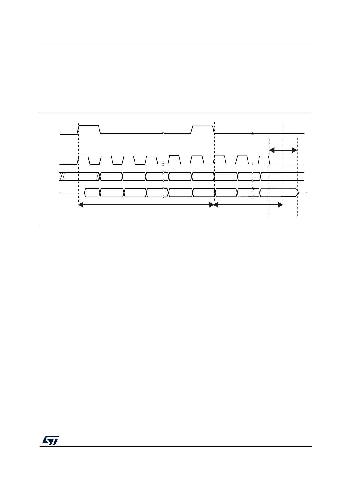
Figure 291 shows the SPI communication waveforms when TI mode is selected.
Figure 291. TI mode transfer
31.4.2 CRC calculation
Two separate CRC calculators (on transmission and reception data flows) are implemented
in order to check the reliability of transmitted and received data. The SPI offers CRC8 or
CRC16 calculation depending on the data format selected through the DFF bit. The CRC is
calculated serially using the polynomial programmed in the SPI_CRCPR register.
CRC principle
CRC calculation is enabled by setting the CRCEN bit in the SPIx_CR1 register before the
SPI is enabled (SPE = 1). The CRC value is calculated using an odd programmable
polynomial on each bit. The calculation is processed on the sampling clock edge defined by
the CPHA and CPOL bits in the SPIx_CR1 register. The calculated CRC value is checked
automatically at the end of the data block as well as for transfer managed by CPU or by the
DMA. When a mismatch is detected between the CRC calculated internally on the received
data and the CRC sent by the transmitter, a CRCERR flag is set to indicate a data corruption
error. The right procedure for handling the CRC calculation depends on the SPI
configuration and the chosen transfer management.
Note: The polynomial value should only be odd. No even values are supported.
CRC transfer managed by CPU
Communication starts and continues normally until the last data frame has to be sent or
received in the SPIx_DR register. Then CRCNEXT bit has to be set in the SPIx_CR1
register to indicate that the CRC frame transaction will follow after the transaction of the
currently processed data frame. The CRCNEXT bit must be set before the end of the last
data frame transaction. CRC calculation is frozen during CRC transaction.
MS19835V2
MSB
MISO
NSS
SCK
trigger
sampling
trigger
sampling
t
rigger
sampling
Do not care
LSB
MOSI
1 or 0 MSB
LSB
MSB LSB
MSB
LSB
FRAME 1
FRAME 2
t
RELEASE