Analog-to-digital converter (ADC) RM0367
308/1043 RM0367 Rev 7
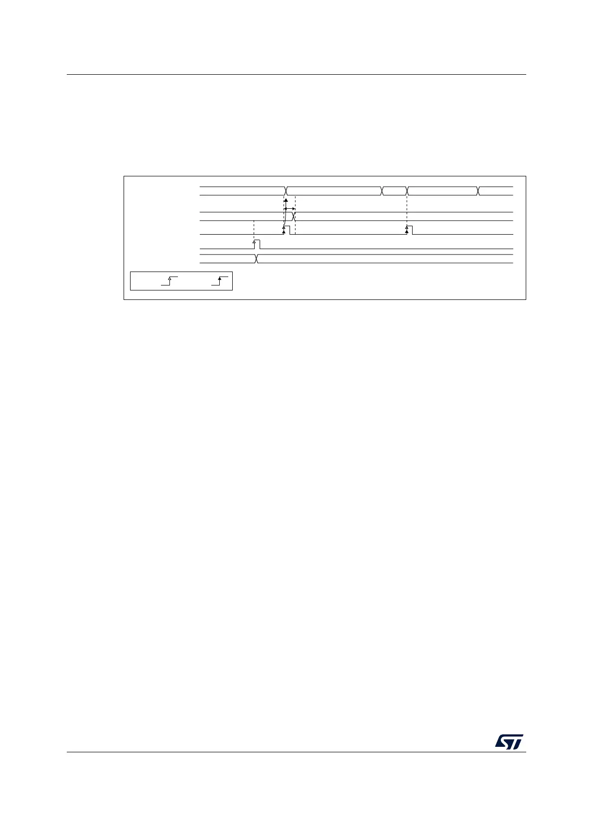
Calibration factor forcing Software procedure
1. Ensure that ADEN= 1 and ADSTART = 0 (ADC started with no conversion ongoing)
2. Write ADC_CALFACT with the saved calibration factor
3. The calibration factor is used as soon as a new conversion is launched.
Figure 33. Calibration factor forcing
14.3.4 ADC on-off control (ADEN, ADDIS, ADRDY)
At power-up, the ADC is disabled and put in power-down mode (ADEN = 0).
As shown in Figure 34, the ADC needs a stabilization time of t
STAB
before it starts
converting accurately.
Two control bits are used to enable or disable the ADC:
• Set ADEN = 1 to enable the ADC. The ADRDY flag is set as soon as the ADC is ready
for operation.
• Set ADDIS = 1 to disable the ADC and put the ADC in power down mode. The ADEN
and ADDIS bits are then automatically cleared by hardware as soon as the ADC is fully
disabled.
If the ADC voltage regulator was not previously set, it is automatically enabled when setting
ADEN=1 (bit ADVREGEN is automatically set by hardware). In this case, the ADC
stabilization time t
STAB
is longer to take into account the stabilization time of the ADC
voltage regulator.
Conversion can then start either by setting ADSTART to 1 (refer to Section 14.4: Conversion
on external trigger and trigger polarity (EXTSEL, EXTEN) on page 316) or when an external
trigger event occurs if triggers are enabled.
Follow this procedure to enable the ADC:
1. Clear the ADRDY bit in ADC_ISR register by programming this bit to 1.
2. Set ADEN = 1 in the ADC_CR register.
3. Wait until ADRDY = 1 in the ADC_ISR register (ADRDY is set after the ADC startup
time). This can be handled by interrupt if the interrupt is enabled by setting the
ADRDYIE bit in the ADC_IER register.
For code example, refer to A.8.2: ADC enable sequence code example.
ADC state
F2
F1
F2
Ready (not converting) Converting channel Ready Converting channel
(Single ended) (Single ended)
Updating
calibration
MS31925V1
by S/W
Internal
calibration factor[6:0]
Start conversion
(hardware or software)
WRITE ADC_CALFACT
CALFACT[6:0]
by H/W