Power control (PWR) RM0367
170/1043 RM0367 Rev 7
6.4.2 PWR power control/status register (PWR_CSR)
Address offset: 0x04
Reset value: 0x0000 0008 (not reset by wakeup from Standby mode)
Additional APB cycles are needed to read this register versus a standard APB read.
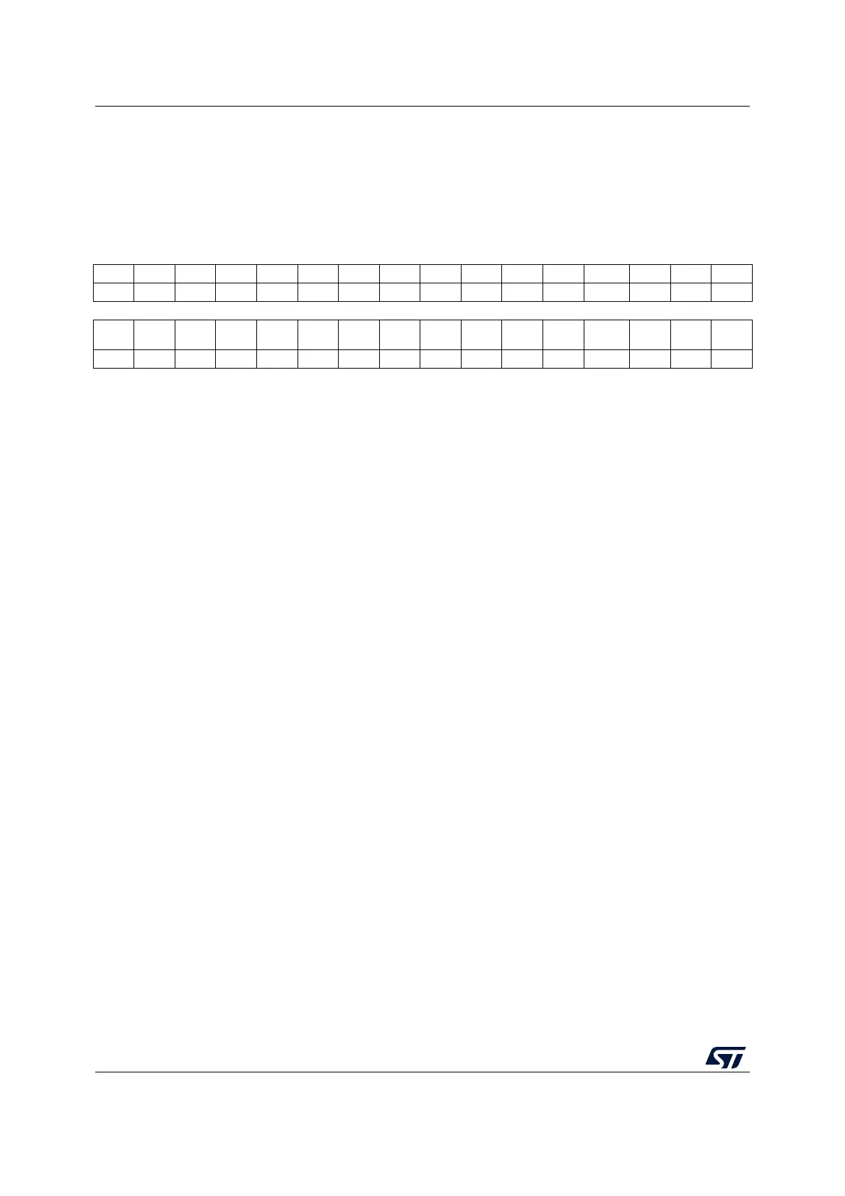
31 30 29 28 27 26 25 24 23 22 21 20 19 18 17 16
Res. Res. Res. Res. Res. Res. Res. Res. Res. Res. Res. Res. Res. Res. Res. Res.
151413121110987654 3 210
Res. Res. Res. Res. Res.
EWUP
3
EWUP
2
EWUP
1
Res. Res.
REG
LPF
VOSF
VREFIN
TRDYF
PVDO SBF WUF
rw rw rw r r r r r r
Bits 31:11 Reserved, must be kept at reset value.
Bit 10 EWUP3: Enable WKUP pin 3
This bit is set and cleared by software.
0: WKUP pin 3 is used for general purpose I/Os. An event on the WKUP pin 3 does not
wakeup the device from Standby mode.
1: WKUP pin 3 is used for wakeup from Standby mode and forced in input pull down
configuration (rising edge on WKUP pin 3wakes-up the system from Standby mode).
Note: This bit is reset by a system reset.
Bit 9 EWUP2: Enable WKUP pin 2
This bit is set and cleared by software.
0: WKUP pin 2 is used for general purpose I/Os. An event on the WKUP pin 2 does not
wakeup the device from Standby mode.
1: WKUP pin 2 is used for wakeup from Standby mode and forced in input pull down
configuration (rising edge on WKUP pin 2 wakes-up the system from Standby mode).
Note: This bit is reset by a system reset.
Bit 8 EWUP1: Enable WKUP pin 1
This bit is set and cleared by software.
0: WKUP pin 1 is used for general purpose I/Os. An event on the WKUP pin 1 does not
wakeup the device from Standby mode.
1: WKUP pin 1 is used for wakeup from Standby mode and forced in input pull down
configuration (rising edge on WKUP pin 1 wakes-up the system from Standby mode).
Note: This bit is reset by a system reset.
Bits 7:6 Reserved, must be kept at reset value.
Bit 5 REGLPF: Regulator LP flag
This bit is set by hardware when the MCU is in Low-power run mode.
When the MCU exits from Low-power run mode, this bit stays at 1 until the regulator is ready in
Main mode. A polling on this bit is recommended to wait for the regulator Main mode. This bit is
reset by hardware when the regulator is ready.
0: Regulator is ready in Main mode
1: Regulator voltage is in low-power mode