RM0367 Rev 7 899/1043
RM0367 Serial peripheral interface/ inter-IC sound (SPI/I2S)
922
The I
2
S interface supports four audio standards, configurable using the I2SSTD[1:0] and
PCMSYNC bits in the SPIx_I2SCFGR register.
I
2
S Philips standard
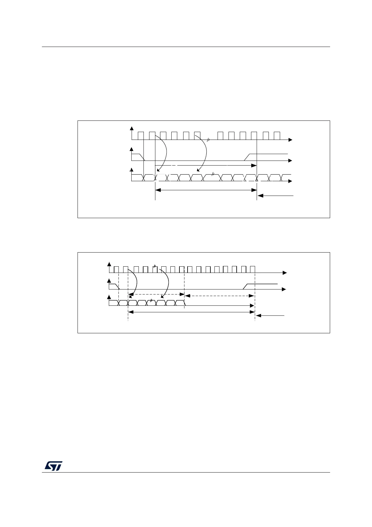
For this standard, the WS signal is used to indicate which channel is being transmitted. It is
activated one CK clock cycle before the first bit (MSB) is available.
Figure 294. I
2
S Philips protocol waveforms (16/32-bit full accuracy, CPOL = 0)
Data are latched on the falling edge of CK (for the transmitter) and are read on the rising
edge (for the receiver). The WS signal is also latched on the falling edge of CK.
Figure 295. I
2
S Philips standard waveforms (24-bit frame with CPOL = 0)
This mode needs two write or read operations to/from the SPIx_DR register.
MS19591V1
CK
WS
SD
Can be 16-bit or 32-bit
MSB
MSBLSB
Channel left
Channel
right
transmission reception
MS19592V1
CK
WS
SD
Transmission Reception
24-bit data
MSB
LSB
Channel left 32-bit
Channel right
8-bit remaining 0 forced