RM0367 Rev 7 573/1043
RM0367 General-purpose timers (TIM21/22)
601
PWM center-aligned mode
Center-aligned mode is active when the CMS bits in TIMx_CR1 register are different from
‘00’ (all the remaining configurations having the same effect on the OCxRef/OCx signals).
The compare flag is set when the counter counts up, when it counts down or both when it
counts up and down depending on the CMS bits configuration. The direction bit (DIR) in the
TIMx_CR1 register is updated by hardware and must not be changed by software. Refer to
the Center-aligned mode (up/down counting) on page 558.
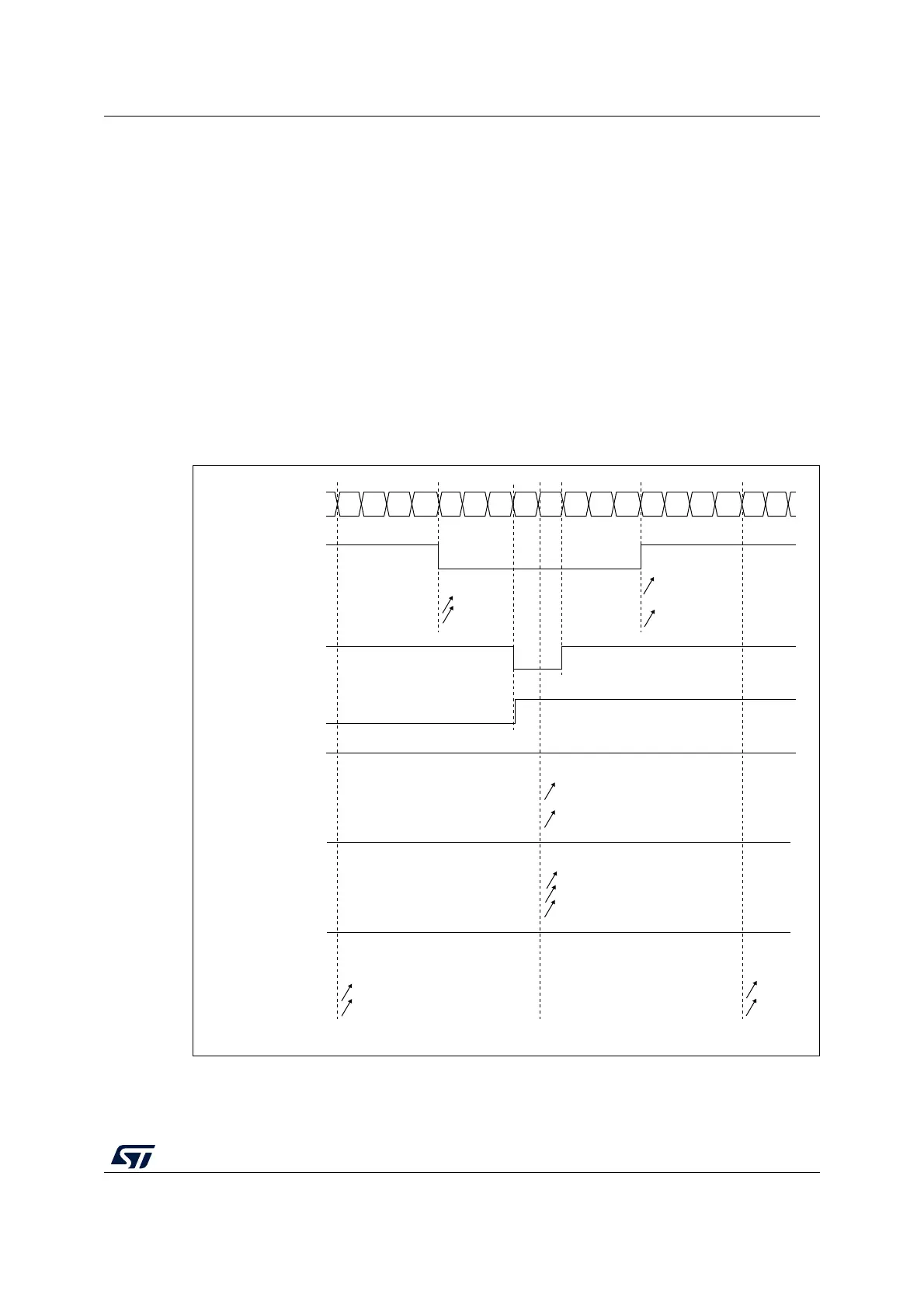
Figure 182 shows some center-aligned PWM waveforms in an example where:
• TIMx_ARR=8,
• PWM mode is the PWM mode 1,
• The flag is set when the counter counts down corresponding to the center-aligned
mode 1 selected for CMS=01 in TIMx_CR1 register.
For code example, refer to A.11.9: Center-aligned PWM configuration example.
Figure 182. Center-aligned PWM waveforms (ARR=8)
CCxIF
012345678765432 101
Counter register
CCRx = 4
OCxREF
CMS=01
CMS=10
CMS=11
CCxIF
CCRx=7
OCxREF
CMS=10 or 11
CCxIF
CCRx=8
OCxREF
CMS=01
CMS=10
CMS=11
‘1’
CCxIF
CCRx>8
OCxREF
CMS=01
CMS=10
CMS=11
‘1’
CCxIF
CCRx=0
OCxREF
CMS=01
CMS=10
CMS=11
‘0’
AI14681b