RM0367 Rev 7 331/1043
RM0367 Analog-to-digital converter (ADC)
352
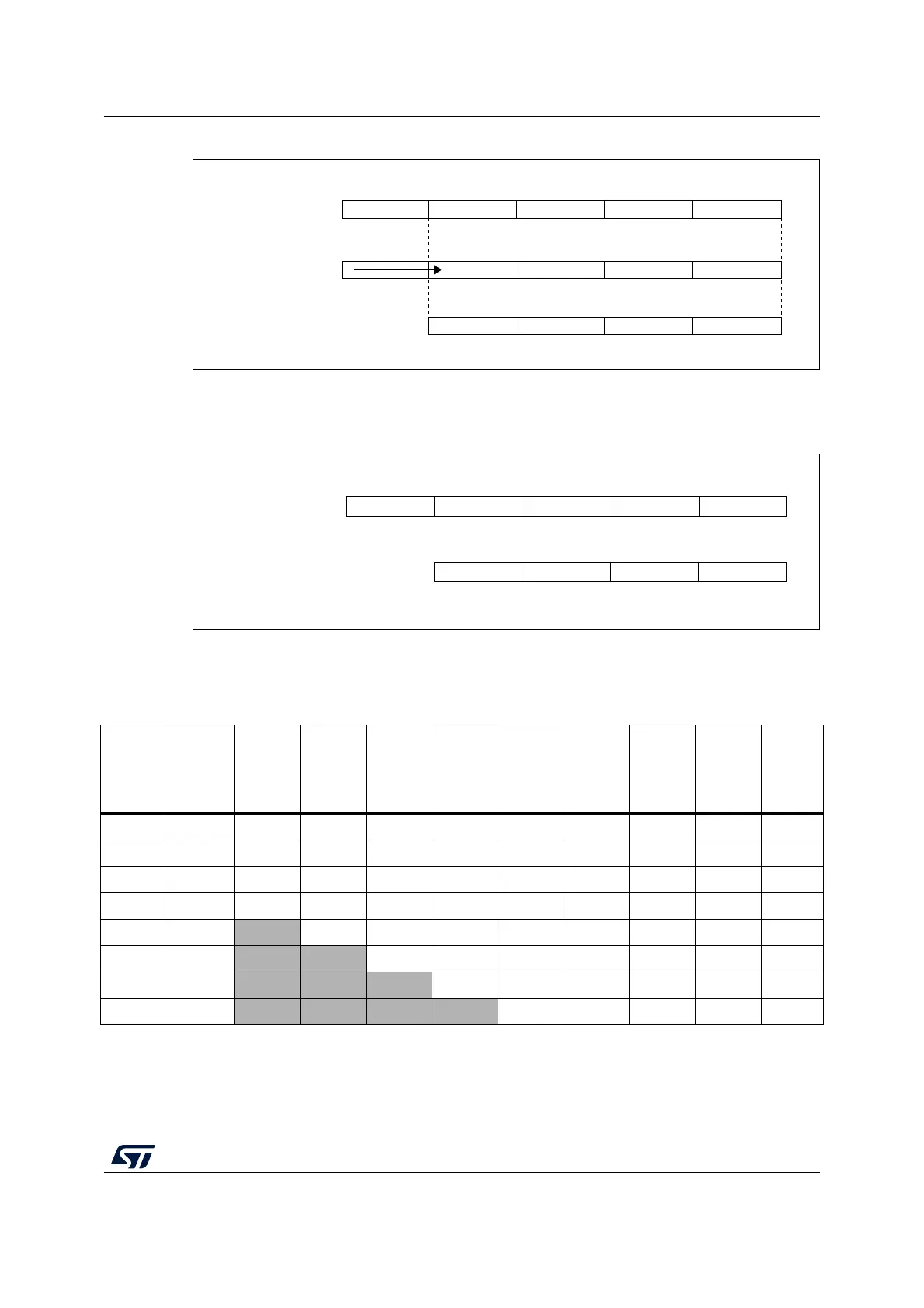
Figure 54. 20-bit to 16-bit result truncation
The Figure 55 gives a numerical example of the processing, from a raw 20-bit accumulated
data to the final 16-bit result.
Figure 55. Numerical example with 5-bits shift and rounding
The Table 66 below gives the data format for the various N and M combination, for a raw
conversion data equal to 0xFFF.
The conversion timings in oversampled mode do not change compared to standard
conversion mode: the sample time is maintained equal during the whole oversampling
037111519
Raw 20-bit data
Truncation
and rounding
Shifting
015
MS31928V2
0
37111519
Raw 20-bit data:
BF
15
B737D
1D
MS31929V1
Final result after 5-bits shift
and rounding to nearest
Table 66. Maximum output results vs N and M. Grayed values indicates truncation
Oversa
mpling
ratio
Max
Raw data
No-shift
OVSS =
0000
1-bit
shift
OVSS =
0001
2-bit
shift
OVSS =
0010
3-bit
shift
OVSS =
0011
4-bit
shift
OVSS =
0100
5-bit
shift
OVSS =
0101
6-bit
shift
OVSS =
0110
7-bit
shift
OVSS =
0111
8-bit
shift
OVSS =
1000
2x 0x1FFE 0x1FFE 0x0FFF 0x0800 0x0400 0x0200 0x0100 0x0080 0x0040 0x0020
4x 0x3FFC 0x3FFC 0x1FFE 0x0FFF 0x0800 0x0400 0x0200 0x0100 0x0080 0x0040
8x 0x7FF8 0x7FF8 0x3FFC 0x1FFE 0x0FFF 0x0800 0x0400 0x0200 0x0100 0x0080
16x 0xFFF0 0xFFF0 0x7FF8 0x3FFC 0x1FFE 0x0FFF 0x0800 0x0400 0x0200 0x0100
32x 0x1FFE0
0xFFE0 0xFFF0 0x7FF8 0x3FFC 0x1FFE 0x0FFF 0x0800 0x0400 0x0200
64x 0x3FFC0
0xFFC0 0xFFE0 0xFFF0 0x7FF8 0x3FFC 0x1FFE 0x0FFF 0x0800 0x0400
128x 0x7FF80
0xFF80 0xFFC0 0xFFE0 0xFFF0 0x7FF8 0x3FFC 0x1FFE 0x0FFF 0x0800
256x 0xFFF00
0xFF00 0xFF80 0xFFC0 0xFFE0 0xFFF0 0x7FF8 0x3FFC 0x1FFE 0x0FFF