Analog-to-digital converter (ADC) RM0367
324/1043 RM0367 Rev 7
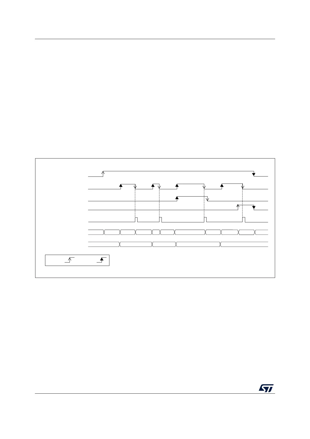
14.6 Low-power features
14.6.1 Wait mode conversion
Wait mode conversion can be used to simplify the software as well as optimizing the
performance of applications clocked at low frequency where there might be a risk of ADC
overrun occurring.
When the WAIT bit is set to 1 in the ADC_CFGR1 register, a new conversion can start only
if the previous data has been treated, once the ADC_DR register has been read or if the
EOC bit has been cleared.
This is a way to automatically adapt the speed of the ADC to the speed of the system that
reads the data.
Note: Any hardware triggers which occur while a conversion is ongoing or during the wait time
preceding the read access are ignored.
Figure 46. Wait mode conversion (continuous mode, software trigger)
1. EXTEN = 00, CONT = 1
2. CHSEL = 0x3, SCANDIR = 0, WAIT = 1, AUTOFF = 0
For code example, refer to A.8.11: Wait mode sequence code example.
MSv30344V2
ADC_DR
by S/W
ADSTP
EOC
ADC state
ADSTART
EOS
CH1 CH2 STOP
CH1CH3 RDYDLYRDY
DLY
ADC_DR Read access
DLY DLY
D1
D3
D1
D2
by H/W