Analog-to-digital converter (ADC) RM0367
336/1043 RM0367 Rev 7
14.10 V
LCD
voltage monitoring
The VLCDEN bit in the ADC_CCR register allows to measure the LCD supply voltage on
the VLCD pin. As the V
LCD
voltage can be higher than V
DDA
, to ensure the correct operation
of the ADC, the VLCD pin is internally connected to a bridge divider. This bridge is
automatically enabled when VLCDEN bit is set, to connect LCD_VLCD1 to the ADC1_IN16
input channel. As a consequence, the converted digital value is either one third of V
LCD
voltage when the LCD is configured to 1/3Bias or a quarter of V
LCD
voltage when the LCD is
configured to 1/4Bias or 1/2Bias. To prevent any unwanted consumption on the battery, it is
recommended to enable the bridge divider only when needed, that is to perform ADC
conversions.
14.11 ADC interrupts
An interrupt can be generated by any of the following events:
• End Of Calibration (EOCAL flag)
• ADC power-up, when the ADC is ready (ADRDY flag)
• End of any conversion (EOC flag)
• End of a sequence of conversions (EOS flag)
• When an analog watchdog detection occurs (AWD flag)
• When the end of sampling phase occurs (EOSMP flag)
• when a data overrun occurs (OVR flag)
Separate interrupt enable bits are available for flexibility.
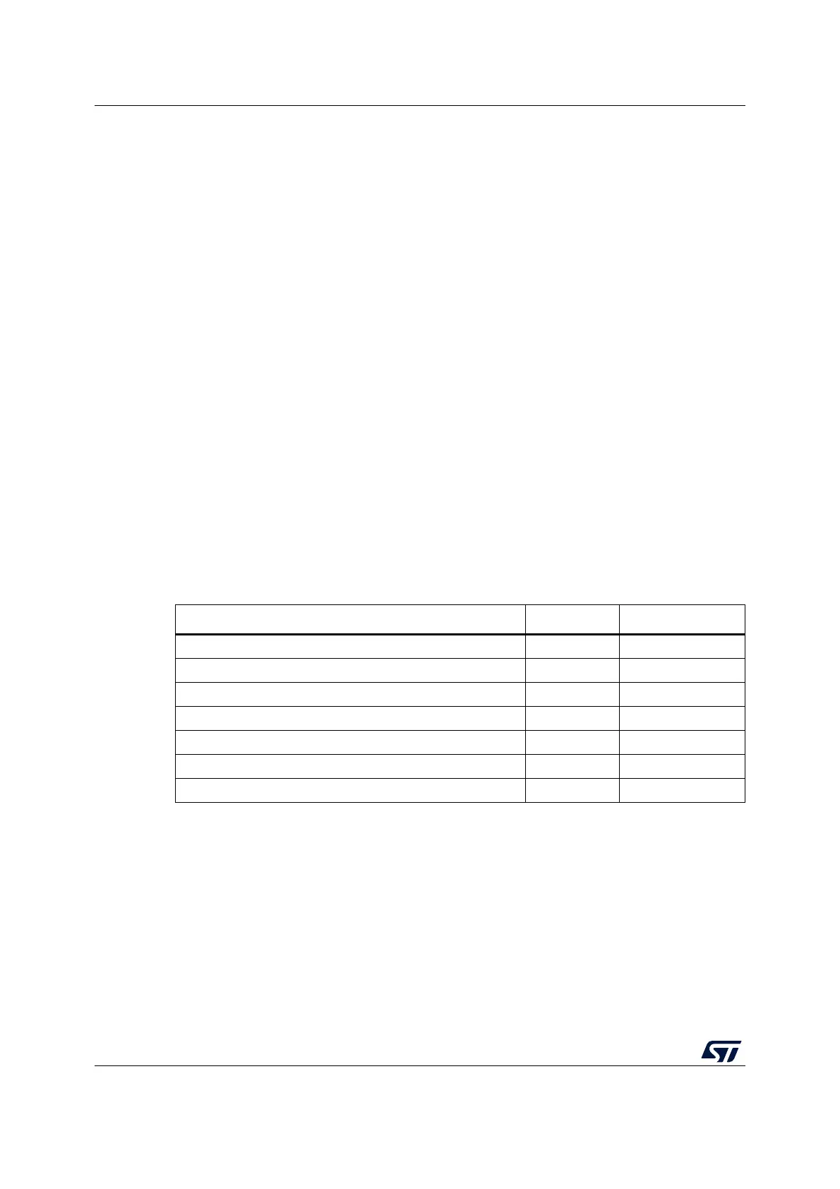
Table 67. ADC interrupts
Interrupt event Event flag Enable control bit
End Of Calibration EOCAL EOCALIE
ADC ready ADRDY ADRDYIE
End of conversion EOC EOCIE
End of sequence of conversions EOS EOSIE
Analog watchdog status bit is set AWD AWDIE
End of sampling phase EOSMP EOSMPIE
Overrun OVR OVRIE