RM0367 Rev 7 185/1043
RM0367 Reset and clock control (RCC)
225
7.2.13 Watchdog clock
If the Independent watchdog (IWDG) is started by either hardware option or software
access, the LSI oscillator is forced ON and cannot be disabled. After the LSI oscillator
temporization, the clock is provided to the IWDG.
If the IWDG was enabled by software, the LSI clock is disabled after system reset. The LSI
oscillator must then be enabled again to ensure correct IWDG operation.
7.2.14 Clock-out capability
The microcontroller clock output (MCO) capability allows the clock to be output onto the
external MCO pin using a configurable prescaler (1, 2, 4, 8, or 16). The configuration
registers of the corresponding GPIO port must be programmed in alternate function mode.
One of 7 clock signals can be selected as the MCO clock:
• SYSCLK
• HSI16
• HSI48
• MSI
• HSE
• PLL
• LSI
• LSE
The selection is controlled by the MCOSEL[3:0] bits of the RCC_CFGR register (see
Section 7.3.20).
For code example, refer to A.4.3: MCO selection code example.
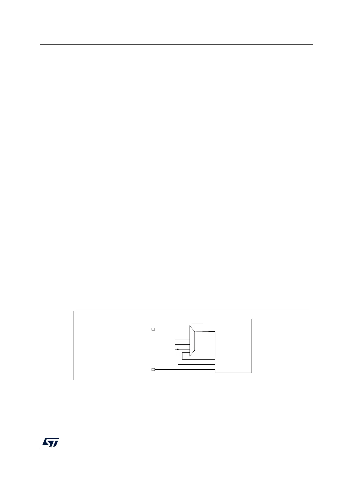
7.2.15 Internal/external clock measurement using TIM21
It is possible to indirectly measure the frequency of all on-board clock source generators by
means of the TIM21 channel 1 input capture, as represented on Figure 18.
Figure 18. Using TIM21 channel 1 input capture to measure
frequencies
TIM21 has an input multiplexer that selects which of the I/O or the internal clock is to trigger
the input capture. This selection is performed through the TI1_RMP [2:0] bits in the
TIM21_OR register.
MS32913V1
GPIO
GPIO
TI1_RMP[2:0]
TIM21
TI(1)
ETR
TI(2)
MSI
LSI
HSE_RTC
LSE
LSE
 Loading...


