RM0367 Rev 7 449/1043
RM0367 AES hardware accelerator (AES)
466
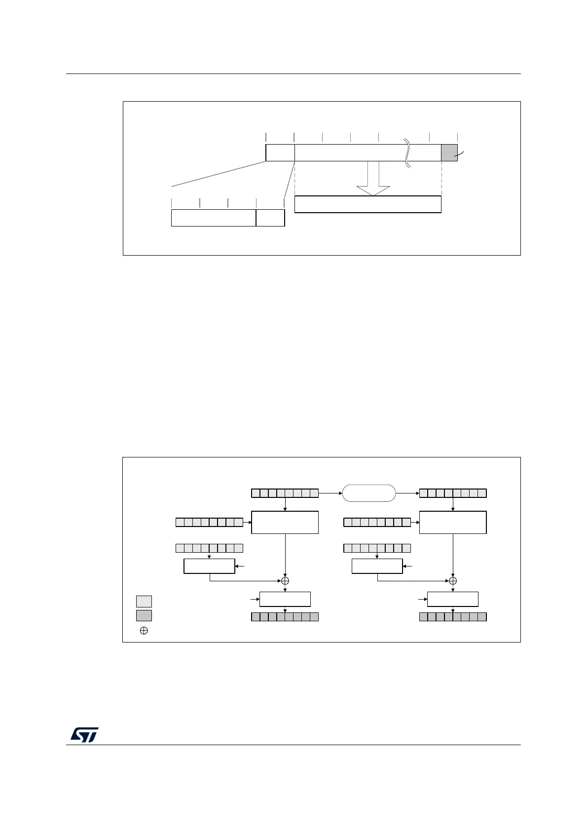
Figure 97. Message construction in CTR mode
The structure of this message is:
• A 16-byte initial counter block (ICB), composed of two distinct fields:
– Initialization vector (IV): a 96-bit value that must be unique for each encryption
cycle with a given key.
– Counter: a 32-bit big-endian integer that is incremented each time a block
processing is completed. The initial value of the counter should be set to 1.
• The plaintext P is encrypted as ciphertext C, with a known length. This length can be
non-multiple of 16 bytes, in which case a plaintext padding is required.
CTR encryption and decryption
Figure 98 and Figure 99 describe the CTR encryption and decryption process, respectively,
as implemented in the AES peripheral. The CTR mode is selected by writing 10 to the
CHMOD[1:0] bitfield of AES_CR register.
Figure 98. CTR encryption
MSv42156V1
16-byte boundaries
ICB Ciphertext (C) 0
4-byte boundaries
CounterInitialization vector (IV)
decrypt
Plaintext (P)
Zero
padding
MSv19102V2
Encrypt
AES_KEYRx (KEY)
AES_DINR (plaintext P1)
AES_DOUTR (ciphertext C1)
DATATYPE[1:0]
Swap
management
AES_IVRx
(IV + 32-bit counter)
input
output
Legend
XOR
Swap
management
DATATYPE[1:0]
Encrypt
AES_KEYRx (KEY)
AES_DOUTR (ciphertext C2)
DATATYPE[1:0]
Swap
management
Swap
management
DATATYPE[1:0]
Counter
increment (+1)
AES_DINR (plaintext P2)
I1
I2
O1 O2
Block 1 Block 2
P1'
P2'
C1'
C2'
AES_IVRx
Nonce + 32-bit counter (+1)