Power control (PWR) RM0367
158/1043 RM0367 Rev 7
6.3.8 Low-power sleep mode (LP sleep)
I/O states in Low-power sleep mode
In Low-power sleep mode, all I/O pins keep the same state as in Run mode.
Entering Low-power sleep mode
To enter Low-power sleep mode, proceed as follows:
1. The Flash memory can be switched off by using the control bits (SLEEP_PD in the
FLASH_ACR register. This reduces power consumption but increases the wake-up
time.
2. Each digital IP clock must be enabled or disabled by using the RCC_APBxENR and
RCC_AHBENR registers.
3. The frequency of the system clock must be decreased.
4. The regulator is forced in low-power mode by software (LPSDSR bits set).
5. Follow the steps described in Section 6.3.5: Entering low-power mode.
Refer to Table 35: Sleep-now (Low-power sleep) and Table 36: Sleep-on-exit (Low-power
sleep) for details on how to enter Low-power sleep mode.
In Low-power sleep mode, the Flash memory can be switched off and the RAM memory
remains available.
In this mode, the system frequency should not exceed f_MSI range1.
Please refer to product datasheet for more details on voltage regulator and peripherals
operating conditions.
Low-power sleep mode can only be entered when V
CORE
is in range 2.
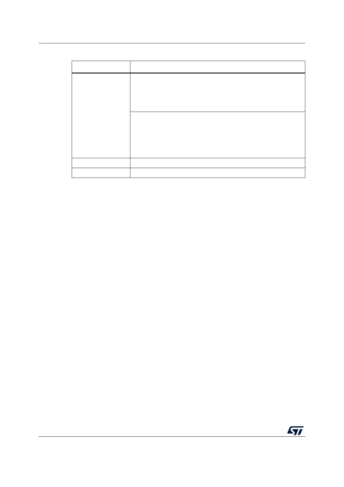
Table 34. Sleep-on-exit
Sleep-on-exit Description
Mode entry
WFI (wait for interrupt) while:
– SLEEPDEEP = 0 and
– No interrupt (for WFI) or event (for WFE) is pending
Refer to the Cortex
®
-M0+ System Control register (see PM0223
programming manual).
On return from ISR while:
– SLEEPDEEP = 0 and
– SLEEPONEXIT = 1 and
– No interrupt is pending
Refer to the Cortex
®
-M0+ System Control register (see PM0223
programming manual).
Mode exit Interrupt: refer to Table 55: List of vectors
Wakeup latency None
 Loading...


