RM0367 Rev 7 511/1043
RM0367 General-purpose timers (TIM2/TIM3)
546
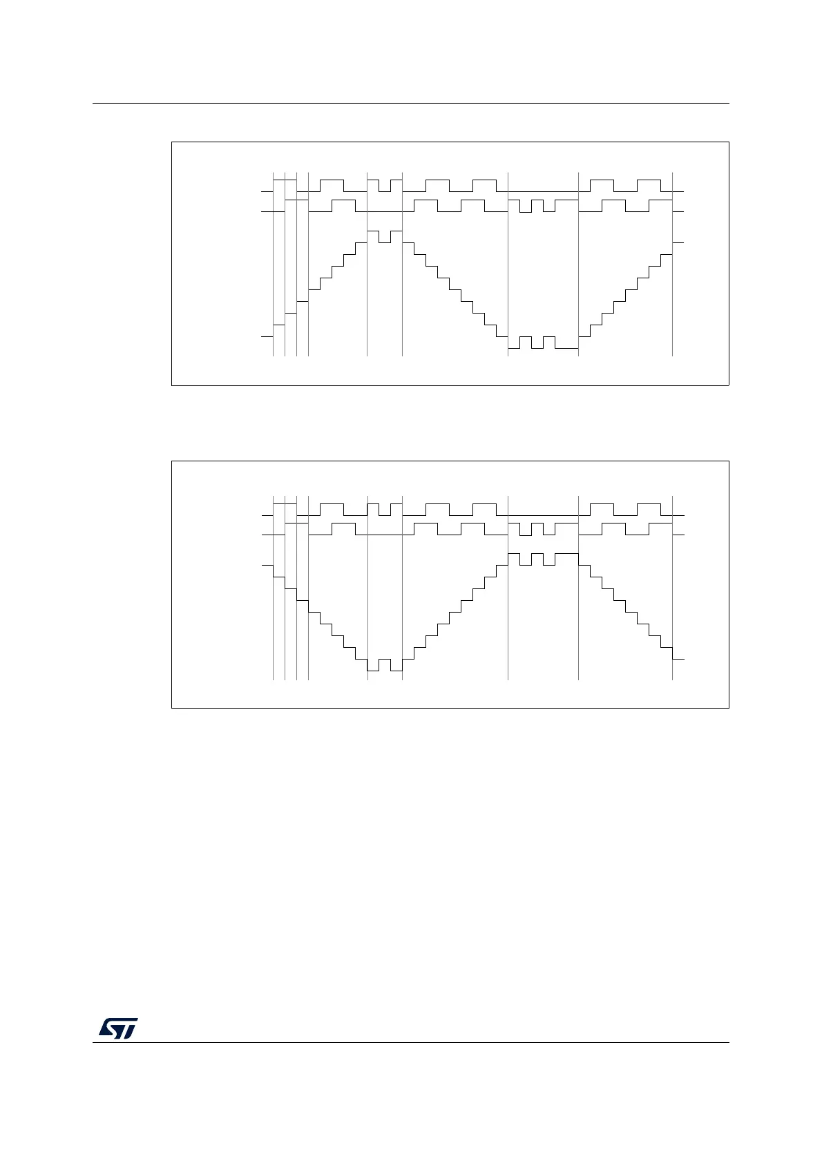
Figure 140. Example of counter operation in encoder interface mode
Figure 141 gives an example of counter behavior when TI1FP1 polarity is inverted (same
configuration as above except CC1P=1).
Figure 141. Example of encoder interface mode with TI1FP1 polarity inverted
The timer, when configured in Encoder Interface mode provides information on the sensor’s
current position. Dynamic information can be obtained (speed, acceleration, deceleration)
by measuring the period between two encoder events using a second timer configured in
capture mode. The output of the encoder which indicates the mechanical zero can be used
for this purpose. Depending on the time between two events, the counter can also be read
at regular times. This can be done by latching the counter value into a third input capture
register if available (then the capture signal must be periodic and can be generated by
another timer). when available, it is also possible to read its value through a DMA request
generated by a Real-Time clock.
21.3.13 Timer input XOR function
The TI1S bit in the TIMx_CR2 register, allows the input filter of channel 1 to be connected to
the output of a XOR gate, combining the three input pins TIMx_CH1 to TIMx_CH3.
The XOR output can be used with all the timer input functions such as trigger or input
capture.
TI1
backwardjitter jitter
up down up
TI2
Counter
forward forward
MS33107V1
TI1
backwardjitter jitter
updown
TI2
Counter
forward forward
MS33108V1
down