Analog-to-digital converter (ADC) RM0367
328/1043 RM0367 Rev 7
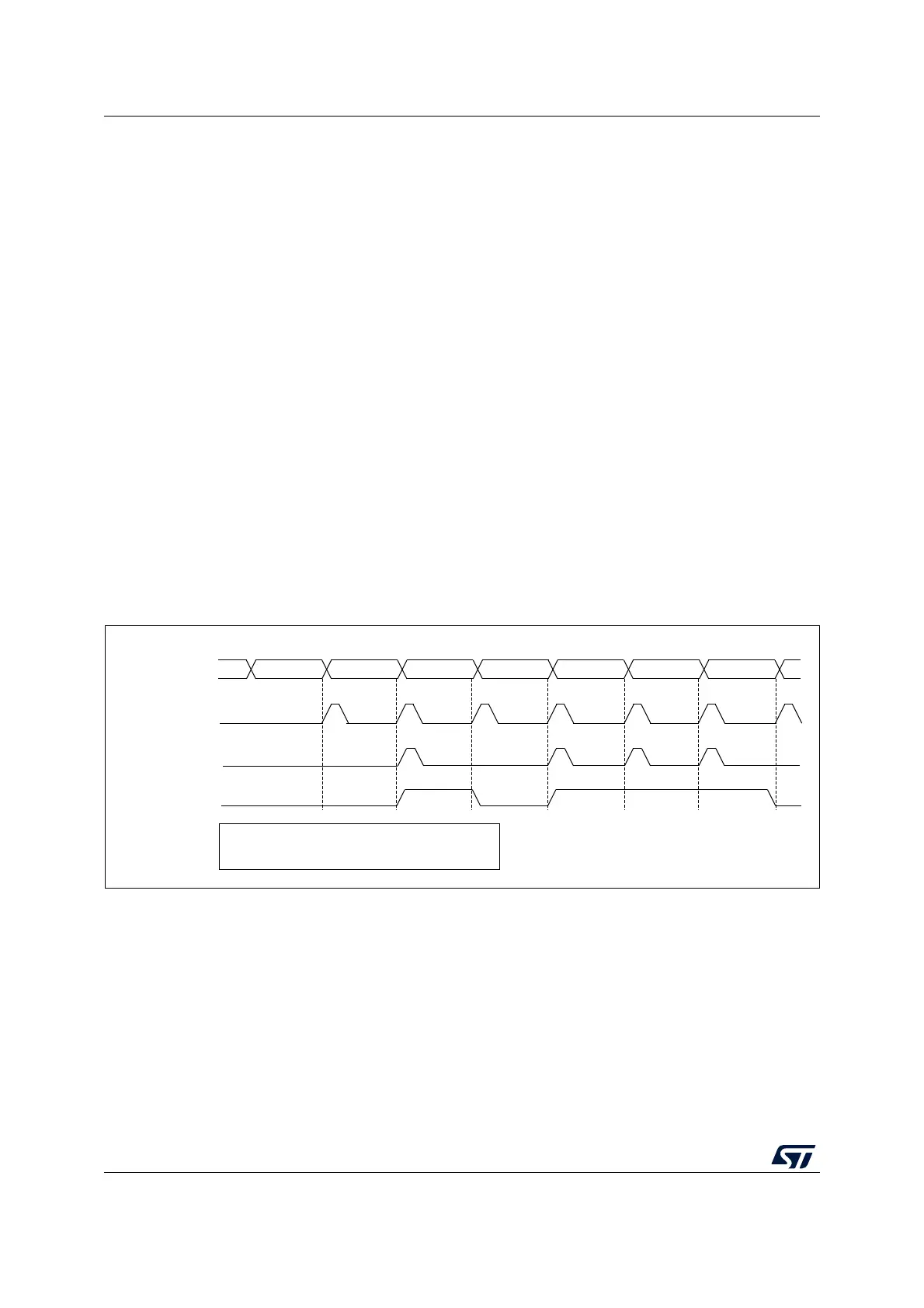
ADC_AWD1_OUT is activated when the analog watchdog is enabled:
• ADC_AWD1_OUT is set when a guarded conversion is outside the programmed
thresholds.
• ADC_AWD1_OUT is reset after the end of the next guarded conversion which is inside
the programmed thresholds. It remains at 1 if the next guarded conversions are still
outside the programmed thresholds.
• ADC_AWD1_OUT is also reset when disabling the ADC (when setting ADDIS to 1).
Note that stopping conversions (ADSTP set to 1), might clear the ADC_AWD1_OUT
state.
• ADC_AWD1_OUT state does not change when the ADC converts the none-guarded
channel (see Figure 50)
AWD flag is set by hardware and reset by software: AWD flag has no influence on the
generation of ADC_AWD1_OUT (as an example, ADC_AWD1_OUT can toggle while AWD
flag remains at 1 if the software has not cleared the flag).
The ADC_AWD1_OUT signal is generated by the ADC_CLK domain. This signal can be
generated even the APB clock is stopped.
The AWD comparison is performed at the end of each ADC conversion. The
ADC_AWD1_OUT rising edge and falling edge occurs two ADC_CLK clock cycles after the
comparison.
As ADC_AWD1_OUT is generated by the ADC_CLK domain and AWD flag is generated by
the APB clock domain, the rising edges of these signals are not synchronized.
Figure 50. ADC_AWD1_OUT signal generation
MSv65326V1
EOC FLAG
ADC STATE
RDY
AWD FLAG
Conversion1
outside
ADC_AWD1_OUT
inside
Cleared
by SW
Conversion2 Conversion3 Conversion4 Conversion5 Conversion6 Conversion7
outsideinside outside outside inside
- Converted channels: 1,2,3,4,5,6,7
- Guarded converted channels: 1,2,3,4,5,6,7
Cleared
by SW
Cleared
by SW
Cleared
by SW
 Loading...


