RM0367 Rev 7 327/1043
RM0367 Analog-to-digital converter (ADC)
352
Table 65 shows how to configure the AWDSGL and AWDEN bits in the ADC_CFGR1
register to enable the analog watchdog on one or more channels.
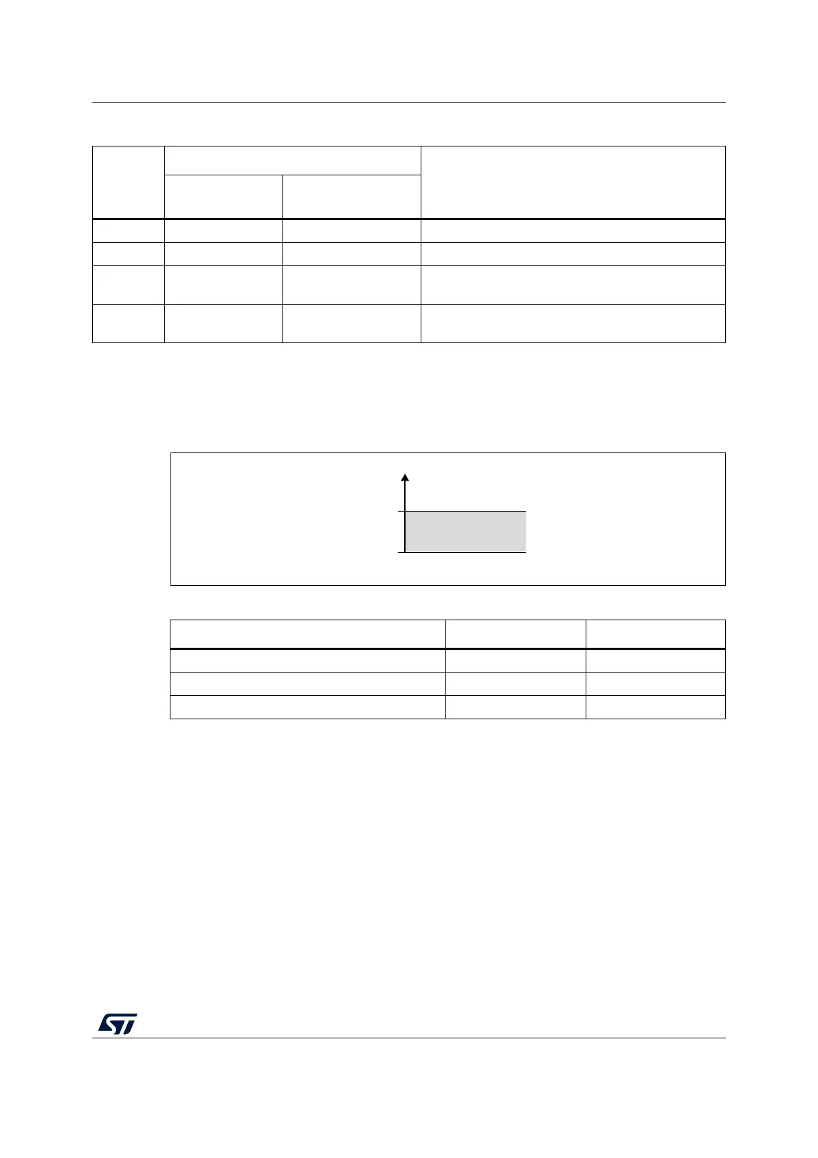
Figure 49. Analog watchdog guarded area
14.7.2 ADC_AWD1_OUT output signal generation
The analog watchdog is associated to an internal hardware signal, ADC_AWD1_OUT that is
directly connected to the ETR input (external trigger) of some on-chip timers (refer to the
timers section for details on how to select the ADC_AWD1_OUT signal as ETR).
Table 64. Analog watchdog comparison
Resolution
bits
RES[1:0]
Analog Watchdog comparison between:
Comments
Raw converted
data, left aligned
(1)
Thresholds
00: 12-bit DATA[11:0] LT[11:0] and HT[11:0] -
01: 10-bit DATA[11:2],00 LT[11:0] and HT[11:0] The user must configure LT1[1:0] and HT1[1:0] to “00”
10: 8-bit DATA[11:4],0000 LT[11:0] and HT[11:0]
The user must configure LT1[3:0] and HT1[3:0] to
“0000”
11: 6-bit DATA[11:6],000000 LT[11:0] and HT[11:0]
The user must configure LT1[5:0] and HT1[5:0] to
“000000”
1. The watchdog comparison is performed on the raw converted data before any alignment calculation.
Table 65. Analog watchdog channel selection
Channels guarded by the analog watchdog AWDSGL bit AWDEN bit
None x 0
All channels 0 1
Single
(1)
channel
1. Selected by the AWDCH[4:0] bits
11
MS45396V1
Analog voltage
Higher threshold
Lower threshold
Guarded area
HTx
LTx