RM0367 Rev 7 397/1043
RM0367 Liquid crystal display controller (LCD)
413
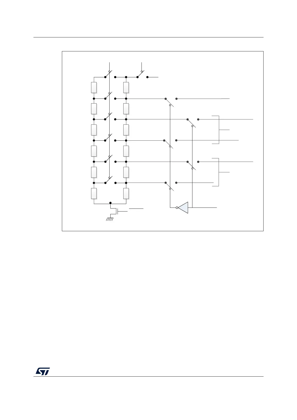
Figure 75. LCD voltage control
1. R
LN
and R
HN
are the low value resistance network and the high value resistance network, respectively.
The R
LN
divider can be always switched on using the HD bit in the LCD_FCR configuration
register (see Section 17.7.2).
The HD switch follows the rules described below:
• If the HD bit and the PON[2:0] bits in the LCD_FCR register are reset, then HD switch
is open.
• If the HD bit in the LCD_FCR register is reset and the PON[2:0] bits in the LCD_FCR
are different from 00 then, the HD switch is closed during the number of pulses defined
in the PON[2:0] bits.
• If HD bit in the LCD_FCR register is 1 then HD switch is always closed.
After the LCDEN bit is activated, the RDY bit is set in the LCD_SR register to indicate that
voltage levels are stable and the LCD controller can start to work.
MS33422V2
3/4 x V
LCD
2/3 x V
LCD
1/2 x V
LCD
1/3 x V
LCD
1/4 x V
LCD
V
LCDRail1
V
LCDRail3
V
LCDRail2
BIAS[1]
3 R
H
3 R
H
R
H
2 R
H
2 R
H
R
H
V
LCD
3 R
L
3 R
L
R
L
2 R
L
2 R
L
R
L
HD
EN
STATIC
V
SS