Universal synchronous/asynchronous receiver transmitter (USART/UART) RM0367
800/1043 RM0367 Rev 7
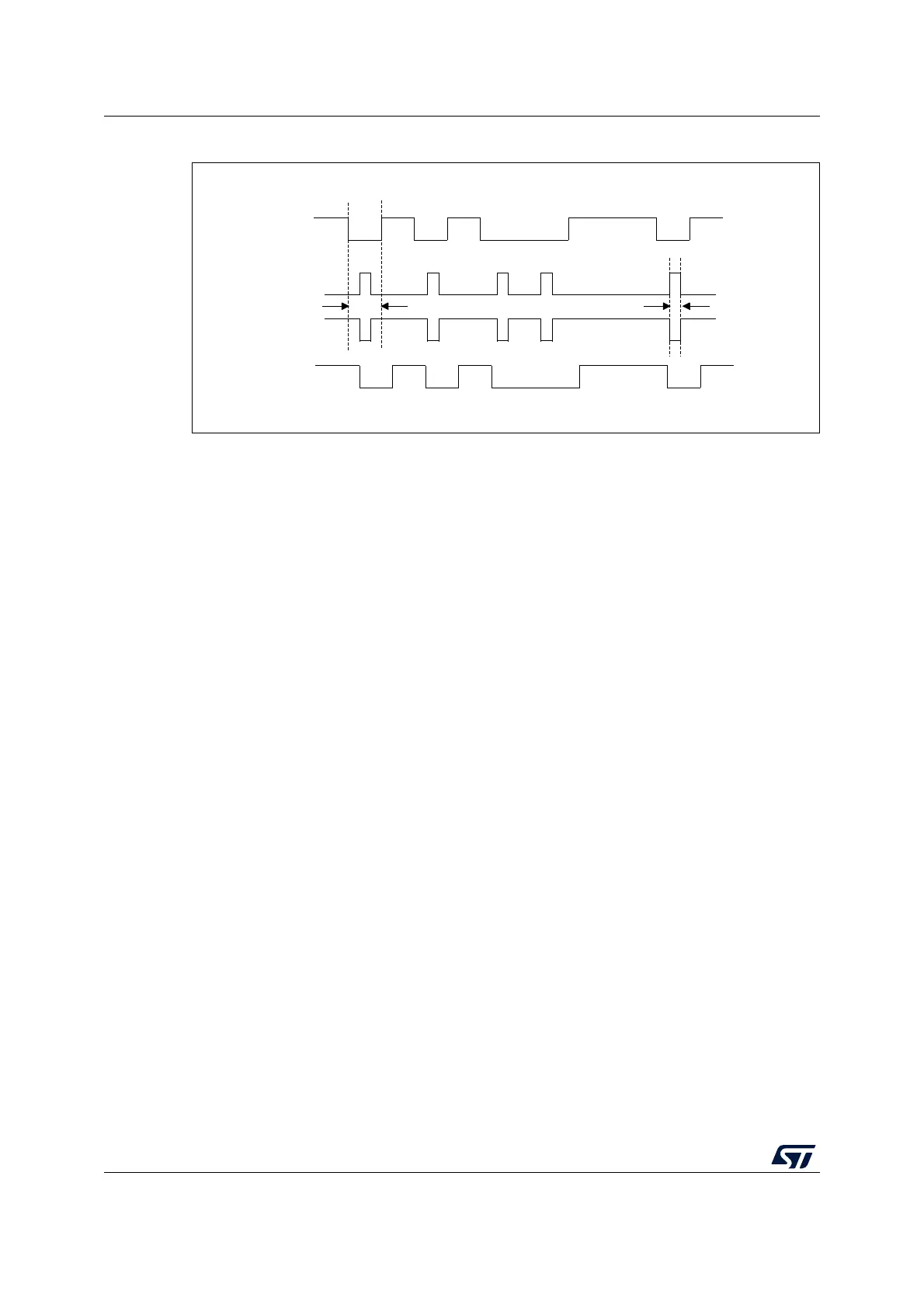
Figure 260. IrDA data modulation (3/16) -Normal Mode
29.5.15 USART continuous communication in DMA mode
The USART is capable of performing continuous communication using the DMA. The DMA
requests for Rx buffer and Tx buffer are generated independently.
Note: Please refer to Section 29.4: USART implementation on page 766 to determine if the DMA
mode is supported. If DMA is not supported, use the USART as explained in Section 29.5.2:
USART transmitter or Section 29.5.3: USART receiver. To perform continuous
communication, the user can clear the TXE/ RXNE flags In the USART_ISR register.
For code example, refer to A.17.11: USART DMA code example.
Transmission using DMA
DMA mode can be enabled for transmission by setting DMAT bit in the USART_CR3
register. Data is loaded from a SRAM area configured using the DMA peripheral (refer to
Section 11: Direct memory access controller (DMA) on page 265) to the USART_TDR
register whenever the TXE bit is set. To map a DMA channel for USART transmission, use
the following procedure (x denotes the channel number):
1. Write the USART_TDR register address in the DMA control register to configure it as
the destination of the transfer. The data is moved to this address from memory after
each TXE event.
2. Write the memory address in the DMA control register to configure it as the source of
the transfer. The data is loaded into the USART_TDR register from this memory area
after each TXE event.
3. Configure the total number of bytes to be transferred to the DMA control register.
4. Configure the channel priority in the DMA register
5. Configure DMA interrupt generation after half/ full transfer as required by the
application.
6. Clear the TC flag in the USART_ISR register by setting the TCCF bit in the
USART_ICR register.
7. Activate the channel in the DMA register.
When the number of data transfers programmed in the DMA Controller is reached, the DMA
controller generates an interrupt on the DMA channel interrupt vector.
MSv31165V1
TX
Start
bit
0101001101
Stop
bit
Bit period
IrDA_OUT
IrDA_IN
RX
3/16
0101 001101