Inter-integrated circuit (I2C) interface RM0367
746/1043 RM0367 Rev 7
Reception using DMA
DMA (direct memory access) can be enabled for reception by setting the RXDMAEN bit in
the I2C_CR1 register. Data is loaded from the I2C_RXDR register to an SRAM area
configured using the DMA peripheral (refer to Section 11: Direct memory access controller
(DMA) on page 265) whenever the RXNE bit is set. Only the data (including PEC) are
transferred with DMA.
• In Master mode, the initialization, the slave address, direction, number of bytes and
START bit are programmed by software. When all data are transferred using DMA, the
DMA must be initialized before setting the START bit. The end of transfer is managed
with the NBYTES counter. For code example refer to A.16.9: I2C configured in slave
mode to receive with DMA code example.
• In Slave mode with NOSTRETCH=0, when all data are transferred using DMA, the
DMA must be initialized before the address match event, or in the ADDR interrupt
subroutine, before clearing the ADDR flag.
• If SMBus is supported (see Section 28.3: I2C implementation): the PEC transfer is
managed with the NBYTES counter. Refer to SMBus Slave receiver on page 737 and
SMBus master receiver on page 741.
Note: If DMA is used for reception, the RXIE bit does not need to be enabled.
28.4.19 Debug mode
When the microcontroller enters debug mode (core halted), the SMBus timeout either
continues to work normally or stops, depending on the DBG_I2Cx_SMBUS_TIMEOUT
configuration bits in the DBG module.
28.5 I2C low-power modes
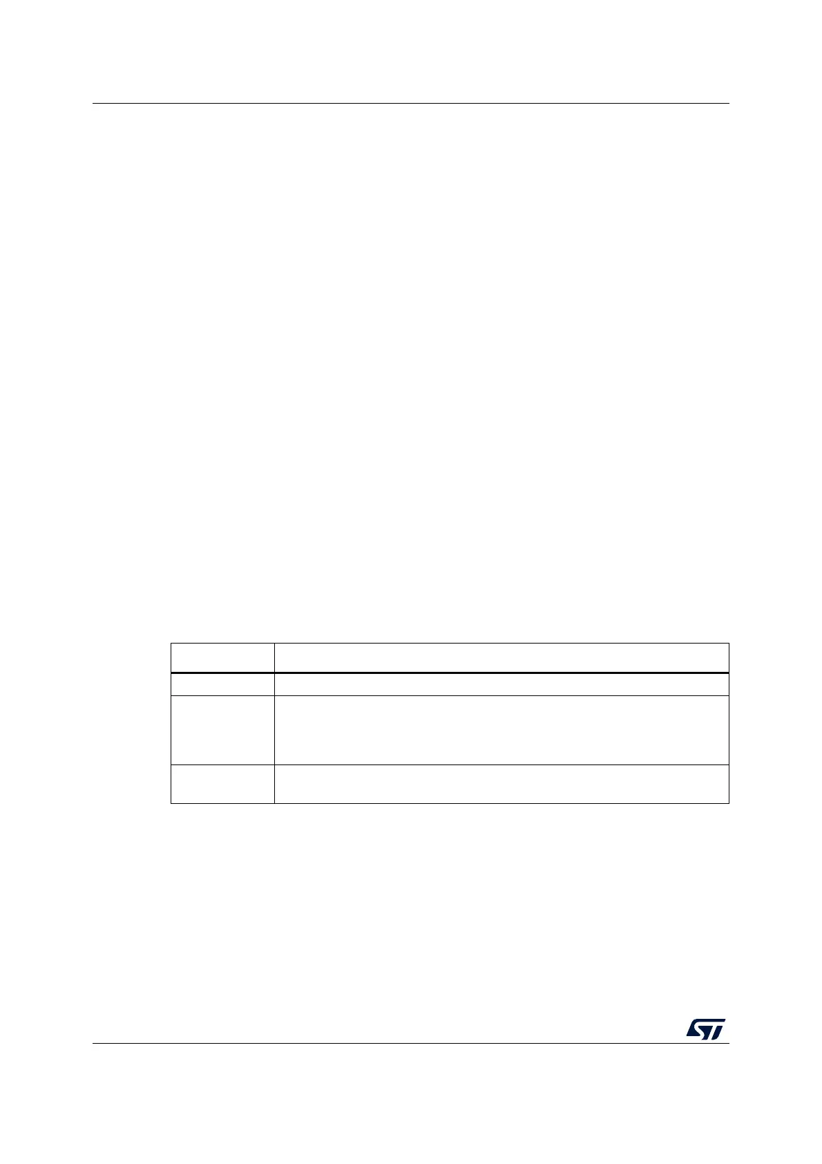
Table 136. Effect of low-power modes on the I2C
Mode Description
Sleep No effect. I2C interrupts cause the device to exit the Sleep mode.
Stop
(1)
1. Refer to Section 28.3: I2C implementation for information about the Stop modes supported by each
instance. If wakeup from a specific Stop mode is not supported, the instance must be disabled before
entering this Stop mode.
The I2C registers content is kept. If WUPEN = 1 and I2C is clocked by an internal
oscillator (HSI16): the address recognition is functional. The I2C address match
condition causes the device to exit the Stop mode. If WUPEN=0: the I2C must be
disabled before entering Stop mode
Standby
The I2C peripheral is powered down and must be reinitialized after exiting
Standby mode.