RM0367 Rev 7 847/1043
RM0367 Low-power universal asynchronous receiver transmitter (LPUART)
872
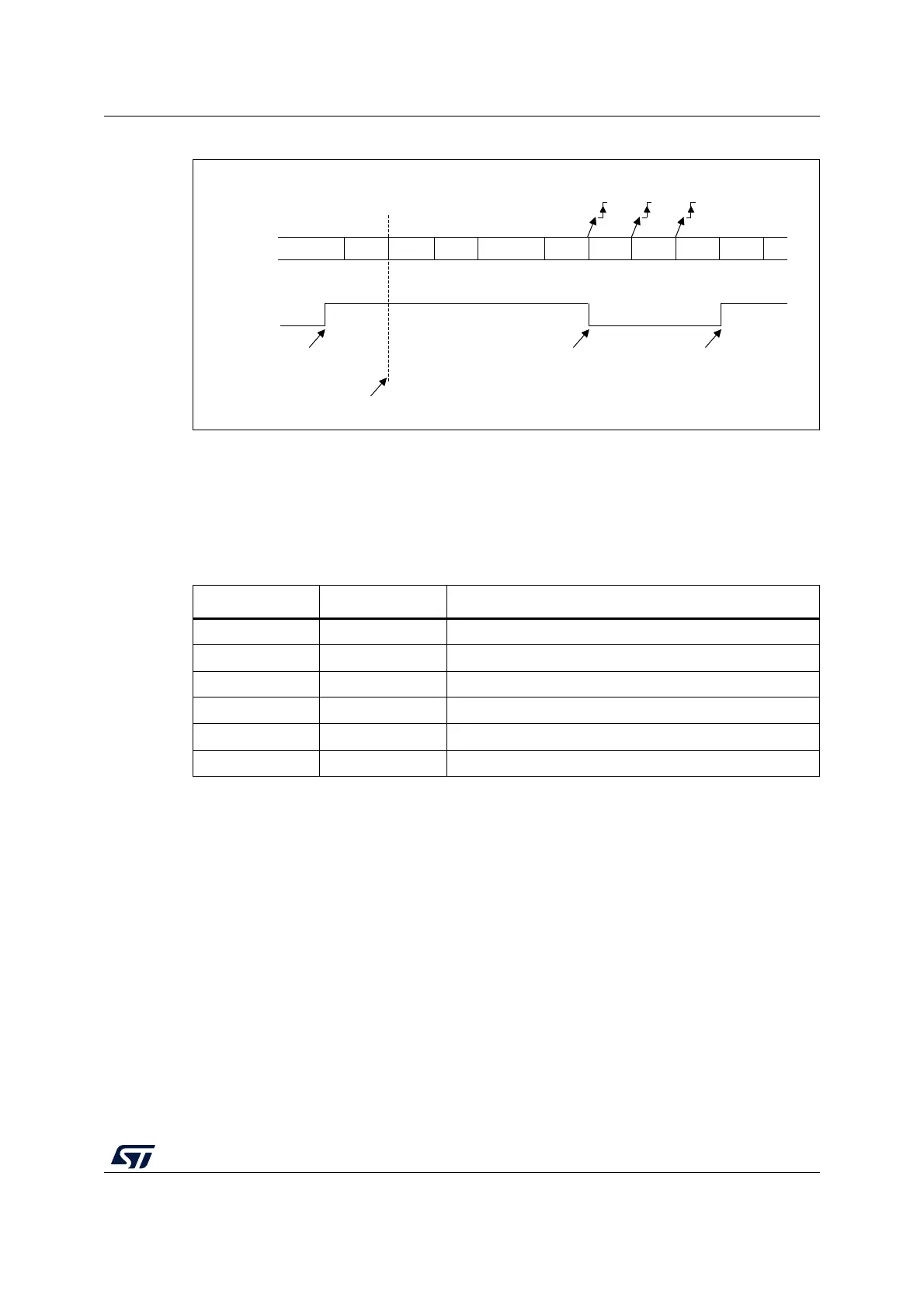
Figure 272. Mute mode using address mark detection
30.4.7 LPUART parity control
Parity control (generation of parity bit in transmission and parity checking in reception) can
be enabled by setting the PCE bit in the LPUART_CR1 register. Depending on the frame
length defined by the M bits, the possible LPUART frame formats are as listed in Table 144.
Even parity
The parity bit is calculated to obtain an even number of “1s” inside the frame which is made
of the 6, 7 or 8 LSB bits (depending on M bits values) and the parity bit.
As an example, if data=00110101, and 4 bits are set, then the parity bit will be 0 if even
parity is selected (PS bit in LPUART_CR1 = 0).
Odd parity
The parity bit is calculated to obtain an odd number of “1s” inside the frame made of the 6, 7
or 8 LSB bits (depending on M bits values) and the parity bit.
As an example, if data=00110101 and 4 bits set, then the parity bit will be 1 if odd parity is
selected (PS bit in LPUART_CR1 = 1).
MSv31888V2
IDLE Addr=0 Data 1 Data 2 IDLE Addr=1 Data 3 Data 4 Addr=2 Data 5
In this example, the current address of the receiver is 1
(programmed in the LPUART_CR2 register)
RXNE
Non-matching addressMatching address
Non-matching address
MMRQ written to 1
(RXNE was cleared)
RWU
RX
Mute mode Mute modeNormal mode
RXNE RXNE
Table 152. Frame formats
M bits PCE bit LPUART frame
(1)
1. Legends: SB: start bit, STB: stop bit, PB: parity bit.
2. In the data register, the PB is always taking the MSB position (9th, 8th or 7th, depending on the M bits
value).
00 0 | SB | 8-bit data | STB |
00 1 | SB | 7-bit data | PB | STB |
01 0 | SB | 9-bit data | STB |
01 1 | SB | 8-bit data | PB | STB |
10 0 | SB | 7-bit data | STB |
10 1 | SB | 6-bit data | PB | STB |
 Loading...


