Analog-to-digital converter (ADC) RM0367
322/1043 RM0367 Rev 7
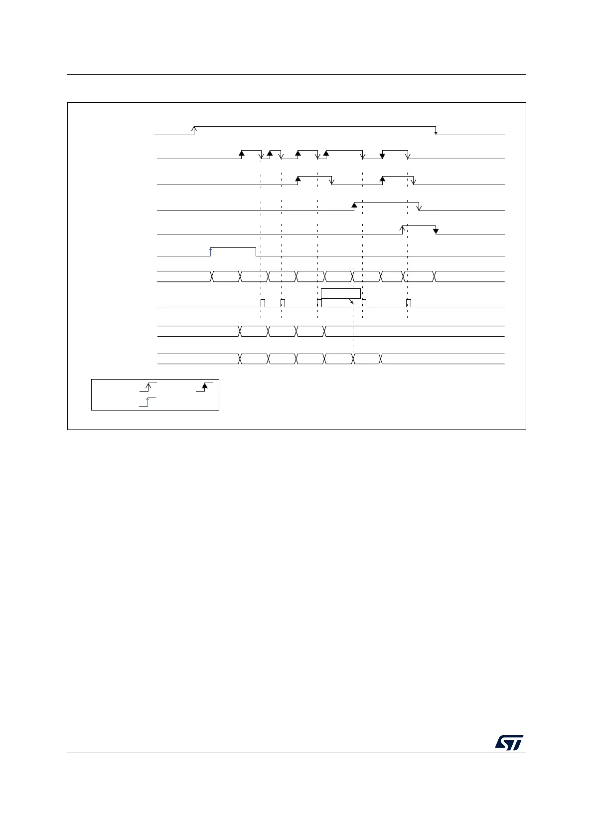
Figure 45. Example of overrun (OVR)
14.5.3 Managing a sequence of data converted without using the DMA
If the conversions are slow enough, the conversion sequence can be handled by software.
In this case the software must use the EOC flag and its associated interrupt to handle each
data result. Each time a conversion is complete, the EOC bit is set in the ADC_ISR register
and the ADC_DR register can be read. The OVRMOD bit in the ADC_CFGR1 register
should be configured to 0 to manage overrun events as an error.
14.5.4 Managing converted data without using the DMA without overrun
It may be useful to let the ADC convert one or more channels without reading the data after
each conversion. In this case, the OVRMOD bit must be configured at 1 and the OVR flag
should be ignored by the software. When OVRMOD = 1, an overrun event does not prevent
the ADC from continuing to convert and the ADC_DR register always contains the latest
conversion data.
14.5.5 Managing converted data using the DMA
Since all converted channel values are stored in a single data register, it is efficient to use
DMA when converting more than one channel. This avoids losing the conversion data
results stored in the ADC_DR register.
When DMA mode is enabled (DMAEN bit set to 1 in the ADC_CFGR1 register), a DMA
request is generated after the conversion of each channel. This allows the transfer of the
MSv30343V3
RDY
EOC
EOS
CH0
CH1 CH2 CH0
D0 D1 D2
CH1 CH2 CH0 STOP
D0
OVR
RDY
D0 D1 D2 D0 D1 D2
ADC_DR read
access
OVERRUN
by S/W by H/W
triggered
ADC_DR
(OVRMOD=0)
ADSTP
ADC state
(2)
ADSTART
(1)
TRGx
(1)
ADC_DR
(OVRMOD=1)
 Loading...


