Universal synchronous/asynchronous receiver transmitter (USART/UART) RM0367
802/1043 RM0367 Rev 7
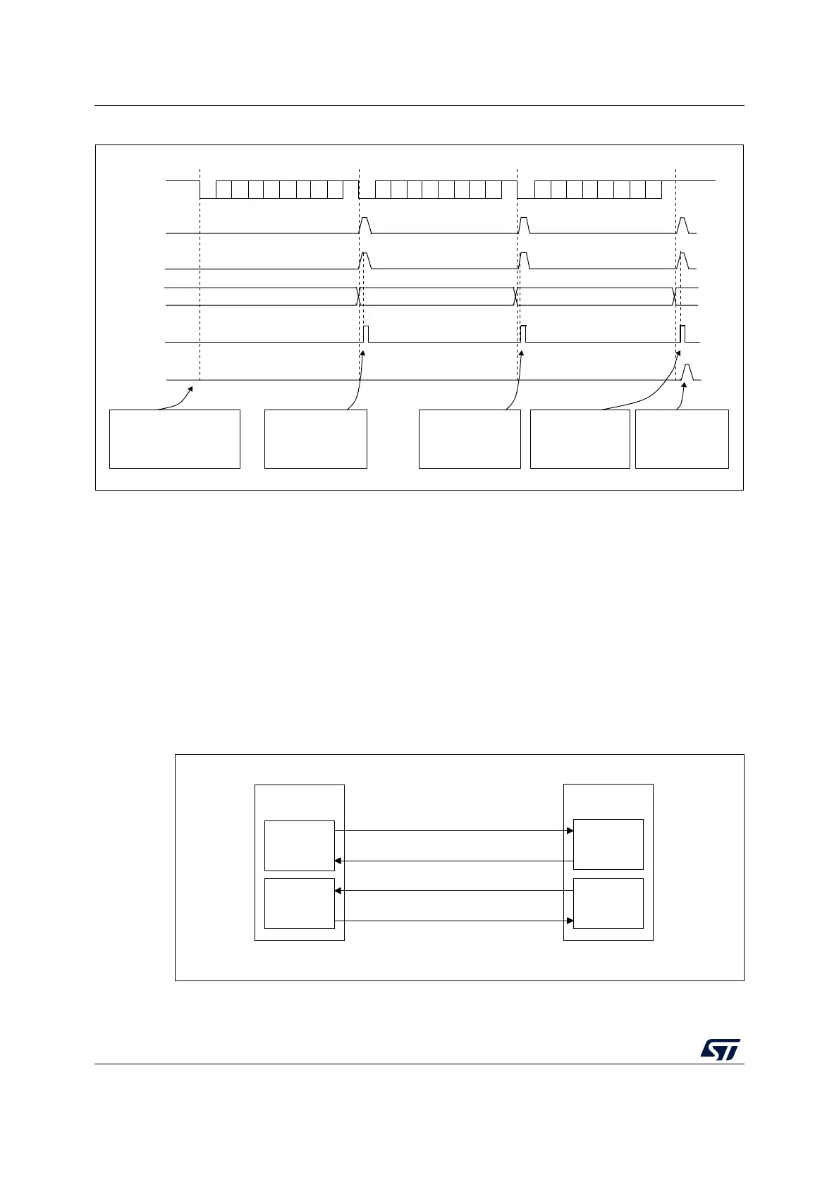
Figure 262. Reception using DMA
Error flagging and interrupt generation in multibuffer communication
In multibuffer communication if any error occurs during the transaction the error flag is
asserted after the current byte. An interrupt is generated if the interrupt enable flag is set.
For framing error, overrun error and noise flag which are asserted with RXNE in single byte
reception, there is a separate error flag interrupt enable bit (EIE bit in the USART_CR3
register), which, if set, enables an interrupt after the current byte if any of these errors occur.
29.5.16 RS232 hardware flow control and RS485 driver enable
using USART
It is possible to control the serial data flow between 2 devices by using the CTS input and
the RTS output. The Figure 263 shows how to connect 2 devices in this mode:
Figure 263. Hardware flow control between 2 USARTs
TX line
Frame 1
F2
F3
Set by hardware
cleared by DMA read
F1
ai17193c
Frame 2
Frame 3
RXNE flag
USART_RDR
DMA request
DMA reads
USART_RDR
DMA TCIF flag
(transfer complete)
Software configures the
DMA to receive 3 data
blocks and enables
the USART
DMA reads F3
from USART_RDR
The DMA transfer
is complete
(TCIF=1 in
DMA_ISR)
Set by hardware
Cleared
by
software
DMA reads F2
from USART_RDR
DMA reads F1
from USART_RDR
MSv31169V2
TX circuit
USART 1
TX
RX circuit
RX circuit
USART 2
TX circuit
TX
CTS
CTSRTS
RX
RTS
RX