RM0367 Rev 7 801/1043
RM0367 Universal synchronous/asynchronous receiver transmitter (USART/UART)
872
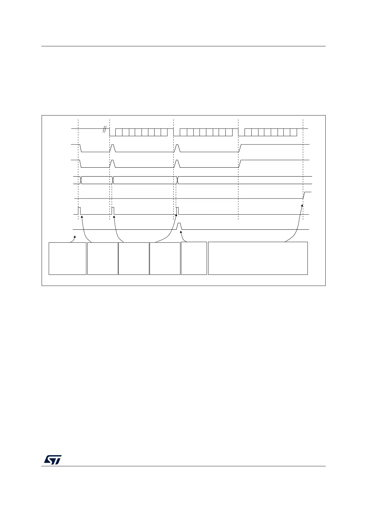
In transmission mode, once the DMA has written all the data to be transmitted (the TCIF flag
is set in the DMA_ISR register), the TC flag can be monitored to make sure that the USART
communication is complete. This is required to avoid corrupting the last transmission before
disabling the USART or entering Stop mode. Software must wait until TC=1. The TC flag
remains cleared during all data transfers and it is set by hardware at the end of transmission
of the last frame.
Figure 261. Transmission using DMA
Reception using DMA
DMA mode can be enabled for reception by setting the DMAR bit in USART_CR3 register.
Data is loaded from the USART_RDR register to a SRAM area configured using the DMA
peripheral (refer to Section 11: Direct memory access controller (DMA) on page 265)
whenever a data byte is received. To map a DMA channel for USART reception, use the
following procedure:
1. Write the USART_RDR register address in the DMA control register to configure it as
the source of the transfer. The data is moved from this address to the memory after
each RXNE event.
2. Write the memory address in the DMA control register to configure it as the destination
of the transfer. The data is loaded from USART_RDR to this memory area after each
RXNE event.
3. Configure the total number of bytes to be transferred to the DMA control register.
4. Configure the channel priority in the DMA control register
5. Configure interrupt generation after half/ full transfer as required by the application.
6. Activate the channel in the DMA control register.
When the number of data transfers programmed in the DMA Controller is reached, the DMA
controller generates an interrupt on the DMA channel interrupt vector.
F2 F3F1
ai17192b
Software
configures DMA
to send 3 data
blocks and
enables USART
The DMA
transfer is
complete
(TCIF=1 in
DMA_ISR)
DMA writes
F1 into
USART_TDR
DMA writes
F2 into
USART_TDR
DMA writes
F3 into
USART_TDR
Software waits until TC=1
Set by hardware
Cleared
by
software
Set by
hardware
TX line
TXE flag
USART_TDR
DMA request
DMA writes
USART_TDR
DMA TCIF flag
(transfer
complete)
TC flag
Frame 1
Frame 2
Frame 3
Idle preamble
Set by hardware
cleared by DMA read
Set by hardware
cleared by DMA read
Set by hardware
Ignored by the DMA because
the transfer is complete
 Loading...


