RM0367 Rev 7 905/1043
RM0367 Serial peripheral interface/ inter-IC sound (SPI/I2S)
922
Note: For both modes (master and slave) and for both synchronizations (short and long), the
number of bits between two consecutive pieces of data (and so two synchronization signals)
needs to be specified (DATLEN and CHLEN bits in the SPIx_I2SCFGR register) even in
slave mode.
31.6.4 Clock generator
The I
2
S bitrate determines the data flow on the I
2
S data line and the I
2
S clock signal
frequency.
I
2
S bitrate = number of bits per channel × number of channels × sampling audio frequency
For a 16-bit audio, left and right channel, the I
2
S bitrate is calculated as follows:
I
2
S bitrate = 16 × 2 × f
S
It will be: I
2
S bitrate = 32 x 2 x f
S
if the packet length is 32-bit wide.
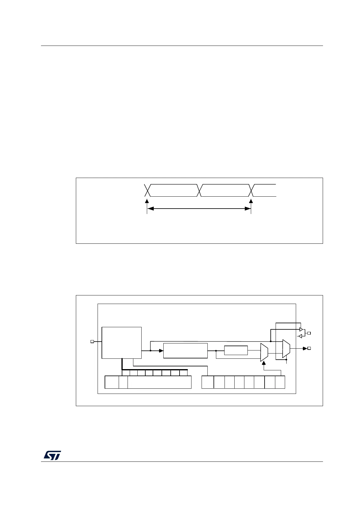
Figure 311. Audio sampling frequency definition
When the master mode is configured, a specific action needs to be taken to properly
program the linear divider in order to communicate with the desired audio frequency.
Figure 312 presents the communication clock architecture. The I2SxCLK clock is provided
by the RCC block, refer to the RCC section for details.
Figure 312. I
2
S clock generator architecture
1. Where x = 2.
MS30108V1
16-or 32-bit left
channel
16-or 32-bit
right channel
32- or 64-bits
sampling point
sampling point
F
S
F
S
: audio sampling frequency
MS30109V1
MCKOE
ODD
8-bit linear divider
+ reshaping stage
Divider by 4
Div2
I²SDIV[7:0]
I²SMOD
CHLEN
0
1
0
1
MCKOE
CK
MCK
I²SxCLK
 Loading...


