RM0367 Rev 7 289/1043
RM0367 Nested vectored interrupt controller (NVIC)
301
12 Nested vectored interrupt controller (NVIC)
12.1 Main features
• Up to 39 maskable interrupt channels (see Table 55), These do not include the 16
interrupt lines of Cortex
®
-M0+.
• 4 programmable priority levels (2 bits of interrupt priority are used)
• Low-latency exception and interrupt handling
• Power management control
• Implementation of system control registers
The NVIC and the processor core interface are closely coupled, which enables low-latency
interrupt processing and efficient processing of late arriving interrupts.
All interrupts including the core exceptions are managed by the NVIC. For more information
on exceptions and NVIC programming, refer to the STM32L0 Series Cortex
®
-M0+
programming manual (PM0223).
For code example, refer to A.7.1: NVIC initialization example.
12.2 SysTick calibration value register
The SysTick calibration value is fixed to 4000, which gives a reference time base of 1 ms
with the SysTick clock set to 4 MHz (max HCLK/8).
12.3 Interrupt and exception vectors
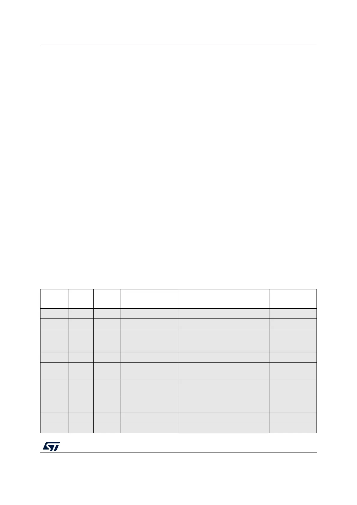
Table 55 is the vector table for STM32L0x3 devices.
Table 55. List of vectors
(1)(2)
Position Priority
Type of
priority
Acronym Description Address
- - - Reserved 0x0000_0000
-3 fixed Reset Reset 0x0000_0004
-2 fixed NMI_Handler
Non maskable interrupt. The RCC
Clock Security System (CSS) is
linked to the NMI vector.
0x0000_0008
-1 fixed HardFault_Handler All class of fault 0x0000_000C
- - - Reserved
0x0000_0010 -
0x0000_002B
3 settable SVC_Handler
System service call via SWI
instruction
0x0000_002C
- - - Reserved
0x0000_0030 -
0x0000_0037
5 settable PendSV_Handler Pendable request for system service 0x0000_0038
6 settable SysTick_Handler System tick timer 0x0000_003C