Digital-to-analog converter (DAC) RM0367
362/1043 RM0367 Rev 7
Simultaneous trigger with different triangle generation
To configure the DAC in this conversion mode ‘refer to Section 15.8: Triangle-wave
generation), the following sequence is required:
1. Set the DAC channelx trigger enable TENx bits.
2. Configure the same trigger source for DAC channelx by setting the same value in the
TSELx[2:0] bits
3. Configure the DAC channelx WAVEx[1:0] bits as “1x” and set different maximum
amplitude values in the MAMPx[3:0] bits.
4. Load the DAC channelx data into the desired DAC_DHRx registers.
When a trigger arrives, the DAC channelx triangle counter, with a triangle amplitude
configured by MAMPx[3:0], is added to the DHRx register and the sum is transferred into
DAC_DORx (three APB clock cycles later). Then the DAC channelx triangle counter is
updated.
15.6.4 DAC output voltage
Refer to Section 15.5.3: DAC output voltage.
15.6.5 DAC trigger selection
Refer to Section 15.5.4: DAC trigger selection
15.7 Noise generation
In order to generate a variable-amplitude pseudonoise, an LFSR (linear feedback shift
register) is available. DAC noise generation is selected by setting WAVEx[1:0] to “01”. The
preloaded value in LFSR is 0xAAA. This register is updated three APB clock cycles after
each trigger event, following a specific calculation algorithm.
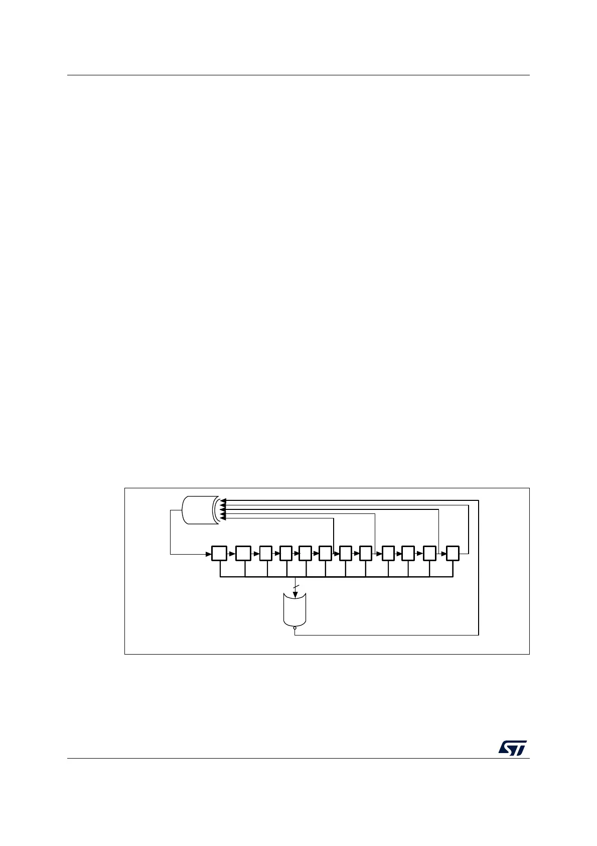
Figure 62. DAC LFSR register calculation algorithm
The LFSR value, that may be masked partially or totally by means of the MAMPx[3:0] bits in
the DAC_CR register, is added up to the DAC_DHRx contents without overflow and this
value is then stored into the DAC_DORx register.
If LFSR is 0x0000, a ‘1 is injected into it (antilock-up mechanism).
11 10 9 8 7 6 5 4 3 2 1 0
12
NOR
X
12
X
0
X
X
4
X
6
XOR
ai14713c