RM0367 Rev 7 457/1043
RM0367 AES hardware accelerator (AES)
466
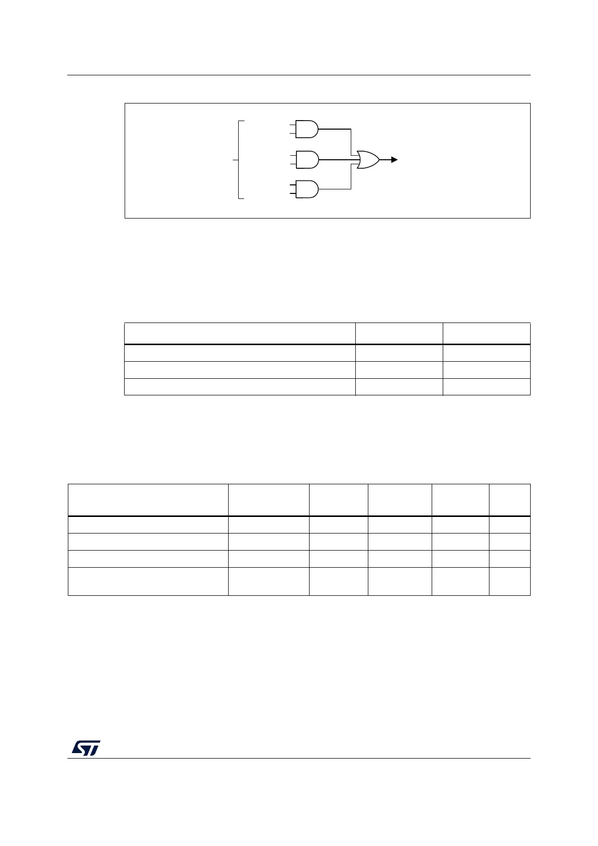
Figure 103. AES interrupt signal generation
Each AES interrupt source can individually be enabled/disabled, by setting/clearing the
corresponding enable bit of the AES_CR register. See Figure 103.
The status of the individual maskable interrupt sources can be read from the AES_SR
register.
Table 92 gives a summary of the interrupt sources, their event flags and enable bits.
19.6 AES processing latency
The tables below summarize the latency to process a 128-bit block for each mode of
operation.
Table 92. AES interrupt requests
AES interrupt event Event flag Enable bit
computation completed flag CCF CCFIE
read error flag RDERR ERRIE
write error flag WRERR ERRIE
MSv42162V1
WRERR
ERRIE
aes_it
(goes to NVIC)
RDERR
ERRIE
CCF
CCFIE
Flags in AES_SR register
Bits of AES_CR register
Table 93. Processing latency (in clock cycle)
Mode of operation Algorithm Input phase
Computation
phase
Output
phase
Total
Mode 1: Encryption ECB, CBC, CTR 8 202 4 214
Mode 2: Key derivation for decryption ECB, CBC - 80 - 80
Mode 3: Decryption ECB, CBC, CTR 8 202 4 214
Mode 4: Key derivation then
decryption
ECB, CBC 8 276 4 288
 Loading...


