System window watchdog (WWDG) RM0367
646/1043 RM0367 Rev 7
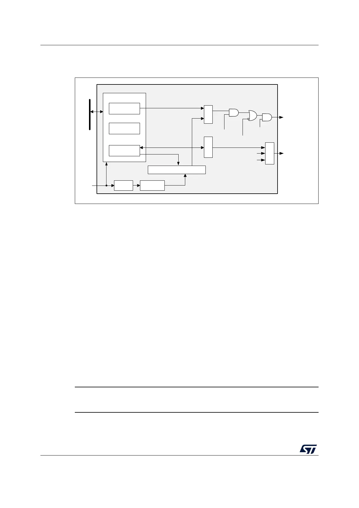
26.3.1 WWDG block diagram
Figure 208. Watchdog block diagram
26.3.2 Enabling the watchdog
The watchdog is always disabled after a reset. It is enabled by setting the WDGA bit in the
WWDG_CR register, then it cannot be disabled again except by a reset.
26.3.3 Controlling the down-counter
This down-counter is free-running, counting down even if the watchdog is disabled. When
the watchdog is enabled, the T6 bit must be set to prevent generating an immediate reset.
The T[5:0] bits contain the number of increments that represent the time delay before the
watchdog produces a reset. The timing varies between a minimum and a maximum value
due to the unknown status of the prescaler when writing to the WWDG_CR register (see
Figure 209). The WWDG configuration register (WWDG_CFR) contains the high limit of the
window: to prevent a reset, the down-counter must be reloaded when its value is lower than
the window register value and greater than 0x3F. Figure 209 describes the window
watchdog process.
Note: The T6 bit can be used to generate a software reset (the WDGA bit is set and the T6 bit is
cleared).
26.3.4 How to program the watchdog timeout
Use the formula in Figure 209 to calculate the WWDG timeout.
Warning: When writing to the WWDG_CR register, always write 1 in the
T6 bit to avoid generating an immediate reset.
MS47214V1
7-bit DownCounter (CNT)
WWDG
pclk
APB bus
÷ 4096 ÷ 2
WDGTB
Write to WWDG_CR
CMP = 1 when
T[6:0] > W[6:0]
CMP
T[6:0]
preload
WWDG_CR
wwdg_out_rst
wwdg_it
= 0x40 ?
readback
WWDG_CFR
W[6:0]
cnt_out
Register interface
WWDG_SR
T6
T[6:0]
WDGA
EWI
Logic
EWIF