RM0367 Rev 7 183/1043
RM0367 Reset and clock control (RCC)
225
7.2.8 System clock (SYSCLK) selection
Four different clock sources can be used to drive the system clock (SYSCLK):
• The HSI16 oscillator
• The HSE oscillator
• The PLL
• The MSI oscillator clock (default after reset)
When a clock source is used directly or through the PLL as system clock, it is not possible to
stop it.
A switch from one clock source to another occurs only if the target clock source is ready
(clock stable after startup delay or PLL locked). If a clock source which is not yet ready is
selected, the switch will occur when the clock source will be ready. Status bits in the
RCC_CR register indicate which clock(s) is (are) ready and which clock is currently used as
system clock.
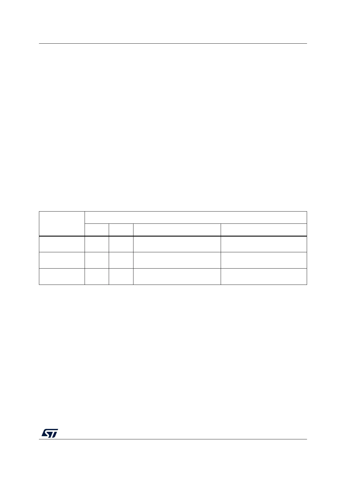
7.2.9 System clock source frequency versus voltage range
The following table gives the different clock source maximum frequencies depending on the
product voltage range.
7.2.10 HSE clock security system (CSS)
The Clock security system can be activated on the HSE by software. In this case, the clock
detector is enabled after the HSE oscillator startup delay, and disabled when this oscillator is
stopped.
If an HSE clock failure is detected, this oscillator is automatically disabled and an CSSHSEI
interrupt (Clock Security System Interrupt) is generated to inform the software of the failure,
thus allowing the MCU to perform rescue operations. The CSSHSEI is linked to the
Cortex
®
-M0+ NMI (Non-Maskable Interrupt) exception vector.
Note: Once the CSSHSE is enabled, if the HSE clock fails, the CSSHSE interrupt occurs and an
NMI is automatically generated. The NMI is executed indefinitely unless the CSSHSE
interrupt pending bit is cleared. As a consequence, the NMI interrupt service routine (ISR)
must clear the CSSHSE interrupt by setting the CSSHSEC bit in the RCC_CICR register.
Table 41. System clock source frequency
Product voltage
range
Clock frequency
MSI HSI16 HSE PLL
Range 1 (1.8 V) 4.2 MHz 16 MHz
HSE 32 MHz (external clock)
or 24 MHz (crystal)
32 MHz
(PLLVCO max = 96 MHz)
Range 2 (1.5 V) 4.2 MHz 16 MHz 16 MHz
16 MHz
(PLLVCO max = 48 MHz)
Range 3 (1.2 V) 4.2 MHz NA 8 MHz
4 MHz
(PLLVCO max = 24 MHz)