Power control (PWR) RM0367
160/1043 RM0367 Rev 7
6.3.9 Stop mode
The Stop mode is based on the Cortex
®
-M0+ Deepsleep mode combined with peripheral
clock gating. The voltage regulator can be configured either in normal or low-power mode.
In Stop mode, all clocks in the V
CORE
domain are stopped, the PLL, the MSI, the HSI16 and
the HSE RC oscillators are disabled. Internal SRAM and register contents are preserved.
To get the lowest consumption in Stop mode, the internal Flash memory also enters low-
power mode. When the Flash memory is in power-down mode, an additional startup delay is
incurred when waking up from Stop mode.
To minimize the consumption In Stop mode, V
REFINT
, the BOR, PVD, and temperature
sensor can be switched off before entering Stop mode. This functionality is controlled by the
ULP bit in the PWR_CR register. If the ULP bit is set, the reference is switched off on Stop
mode entry and enabled again on wakeup. .
I/O states in Low-power sleep mode
In Stop mode, all I/O pins keep the same state as in Run mode.
Entering Stop mode
Refer to Section 6.3.5: Entering low-power mode and to Table 37 for details on how to enter
the Stop mode.
If the application needs to disable the external clock before entering Stop mode, the HSEON
bit must be first disabled and the system clock switched to HSI16.
Otherwise, if the HSEON bit is kept enabled while external clock (external oscillator) can be
removed before entering Stop mode, the clock security system (CSS) feature must be
enabled to detect any external oscillator failure and avoid a malfunction behavior when
entering Stop mode.
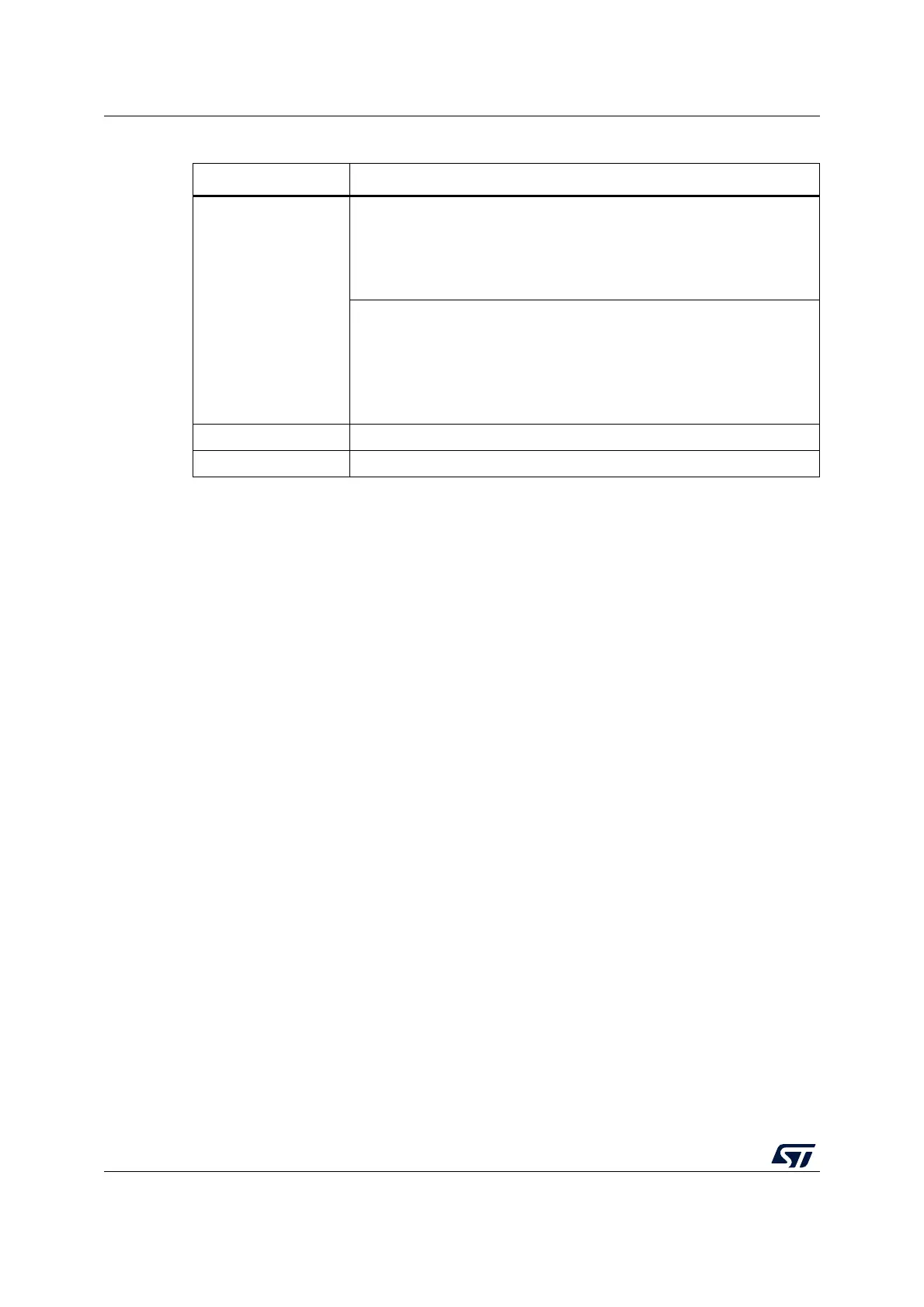
Table 36. Sleep-on-exit (Low-power sleep)
Sleep-on-exit Description
Mode entry
WFI (wait for interrupt) while:
– SLEEPDEEP = 0 and
– No interrupt (for WFI) or event (for WFE) is pending
Refer to the Cortex
®
-M0+ System Control register (see PM0223
programming manual).
On return from ISR while:
– SLEEPDEEP = 0 and
– SLEEPONEXIT = 1 and
– No interrupt is pending
Refer to the Cortex
®
-M0+ System Control register (see PM0223
programming manual).
Mode exit Interrupt: refer to Table 55: List of vectors.
Wakeup latency regulator wakeup time from low-power mode
 Loading...


