Universal synchronous/asynchronous receiver transmitter (USART/UART) RM0367
772/1043 RM0367 Rev 7
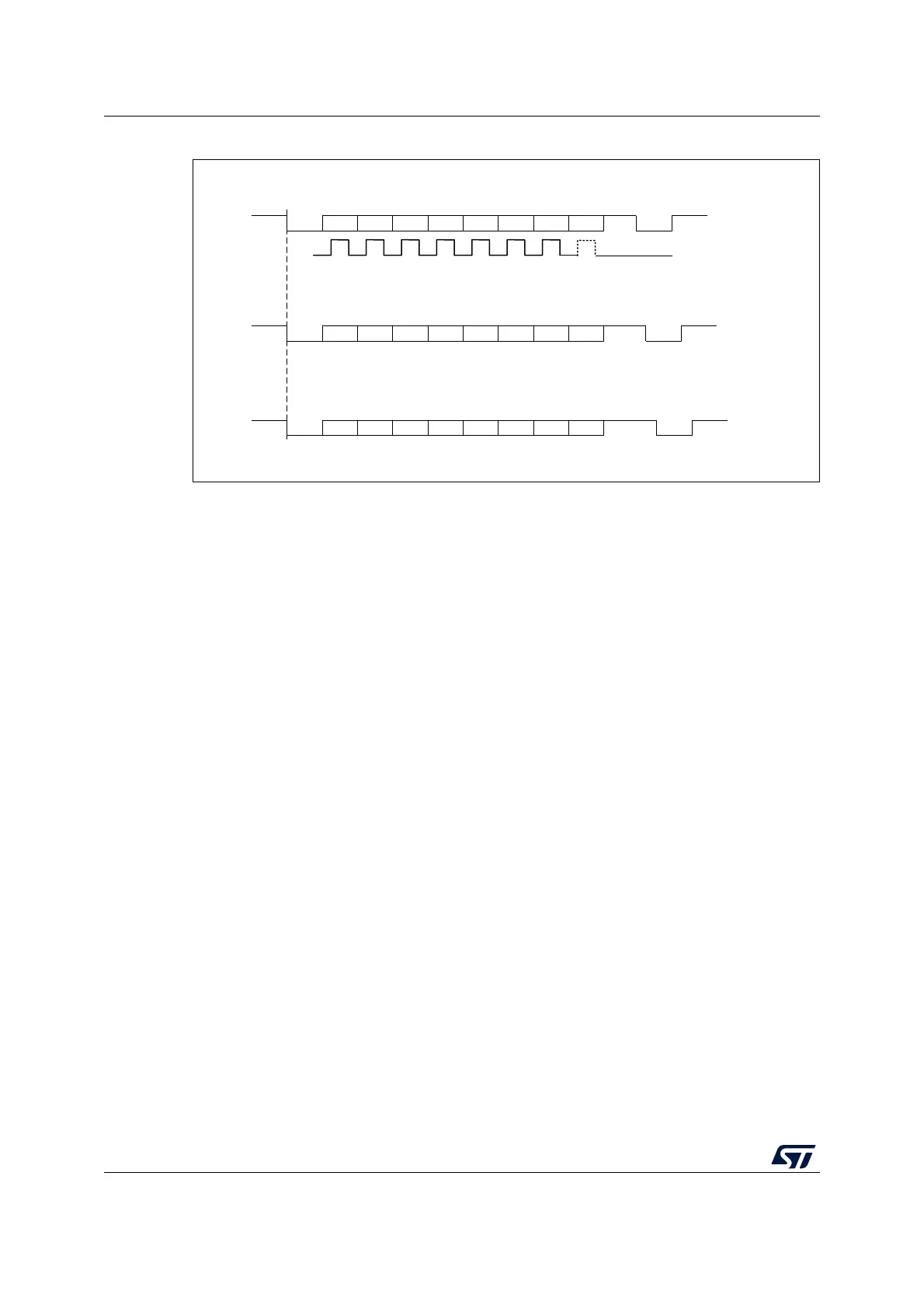
Figure 244. Configurable stop bits
Character transmission procedure
1. Program the M bits in USART_CR1 to define the word length.
2. Select the desired baud rate using the USART_BRR register.
3. Program the number of stop bits in USART_CR2.
4. Enable the USART by writing the UE bit in USART_CR1 register to 1.
5. Select DMA enable (DMAT) in USART_CR3 if multibuffer communication is to take
place. Configure the DMA register as explained in multibuffer communication.
6. Set the TE bit in USART_CR1 to send an idle frame as first transmission.
7. Write the data to send in the USART_TDR register (this clears the TXE bit). Repeat this
for each data to be transmitted in case of single buffer.
8. After writing the last data into the USART_TDR register, wait until TC=1. This indicates
that the transmission of the last frame is complete. This is required for instance when
the USART is disabled or enters the Halt mode to avoid corrupting the last
transmission.
For code example, refer to A.17.1: USART transmitter configuration code example.
Single byte communication
Clearing the TXE bit is always performed by a write to the transmit data register.
The TXE bit is set by hardware and it indicates:
• The data has been moved from the USART_TDR register to the shift register and the
data transmission has started.
• The USART_TDR register is empty.
• The next data can be written in the USART_TDR register without overwriting the
previous data.
For code example, refer to A.17.2: USART transmit byte code example.
This flag generates an interrupt if the TXEIE bit is set.
MSv31887V1
** LBCL bit controls last data clock pulse
Bit7Start bit
Stop
bit
Next
start
bit
Possible
parity bit
Data frame
Next data frame
CLOCK
**
Next data frame
8-bit data, 1 Stop bit
8-bit data, 1 1/2 Stop bits
8-bit data, 2 Stop bits
Bit6Bit5Bit4Bit3Bit2Bit1Bit0
Bit7Start bit
1.5
Stop
bits
Next
start
bit
Possible
parity bit
Data frame
Bit6Bit5Bit4Bit3Bit2Bit1Bit0
Next data frame
Bit7Start bit
2
Stop
bits
Next
start
bit
Possible
parity bit
Data frame
Bit6Bit5Bit4Bit3Bit2Bit1Bit0
 Loading...


