Low-power universal asynchronous receiver transmitter (LPUART) RM0367
858/1043 RM0367 Rev 7
30.7 LPUART registers
Refer to Section 1.2 on page 52 for a list of abbreviations used in register descriptions.
The peripheral registers have to be accessed by words (32 bits).
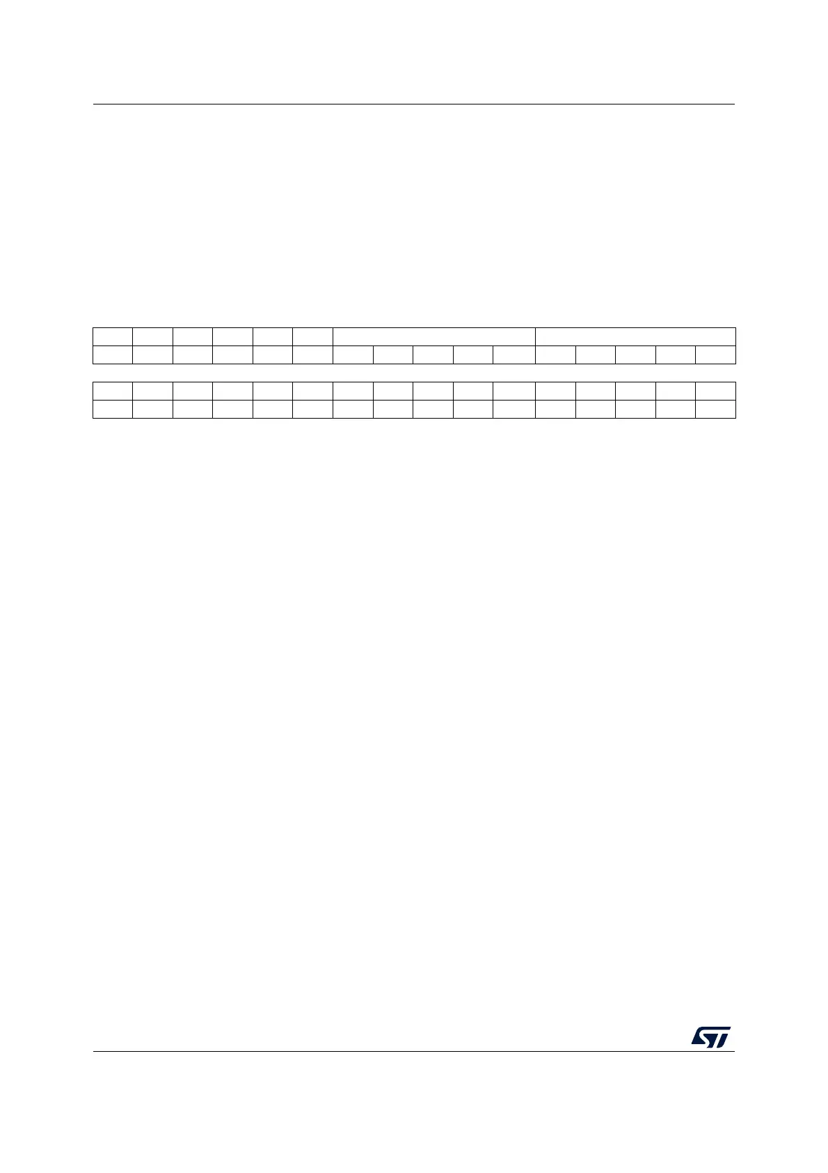
30.7.1 Control register 1 (LPUART_CR1)
Address offset: 0x00
Reset value: 0x0000
31 30 29 28 27 26 25 24 23 22 21 20 19 18 17 16
Res. Res. Res. M1 Res. Res. DEAT[4:0] DEDT[4:0]
rw rw rw rw rw rw rw rw rw rw rw
15141312111098765 43210
Res. CMIE MME M0 WAKE PCE PS PEIE TXEIE TCIE RXNEIE IDLEIE TE RE UESM UE
rw rw rw rw rw rw rw rw rw rw rw rw rw rw rw
Bits 31:29 Reserved, must be kept at reset value
Bit 28 M1: Word length
This bit, with bit 12 (M0) determines the word length. It is set or cleared by software.
M[1:0] = 00: 1 Start bit, 8 data bits, n stop bits
M[1:0] = 01: 1 Start bit, 9 data bits, n stop bits
M[1:0] = 10: 1 Start bit, 7 data bits, n stop bits
This bit can only be written when the LPUART is disabled (UE=0).
Bit 27 Reserved, must be kept at reset value
Bit 26 Reserved, must be kept at reset value
Bits 25:21 DEAT[4:0]: Driver Enable assertion time
This 5-bit value defines the time between the activation of the DE (Driver Enable) signal and
the beginning of the start bit. It is expressed in UCLK (USART clock) clock cycles. For more
details, refer to RS485 Driver Enable paragraph.
This bit field can only be written when the LPUART is disabled (UE=0).
Bits 20:16 DEDT[4:0]: Driver Enable de-assertion time
This 5-bit value defines the time between the end of the last stop bit, in a transmitted
message, and the de-activation of the DE (Driver Enable) signal. It is expressed in UCLK
(USART clock) clock cycles. For more details, refer to RS485 Driver Enable paragraph.
If the LPUART_TDR register is written during the DEDT time, the new data is transmitted
only when the DEDT and DEAT times have both elapsed.
This bit field can only be written when the LPUART is disabled (UE=0).
Bit 15 Reserved, must be kept at reset value
Bit 14 CMIE: Character match interrupt enable
This bit is set and cleared by software.
0: Interrupt is inhibited
1: A LPUART interrupt is generated when the CMF bit is set in the LPUART_ISR register.
 Loading...


