Inter-integrated circuit (I2C) interface RM0367
756/1043 RM0367 Rev 7
28.7.6 I2C timeout register (I2C_TIMEOUTR)
Address offset: 0x14
Reset value: 0x0000 0000
Access: No wait states, except if a write access occurs while a write access to this register is
ongoing. In this case, wait states are inserted in the second write access until the previous
one is completed. The latency of the second write access can be up to 2 x PCLK1 + 6 x
I2CCLK.
Note: If the SMBus feature is not supported, this register is reserved and forced by hardware to
“0x00000000”.
Refer to Section 28.3: I2C implementation.
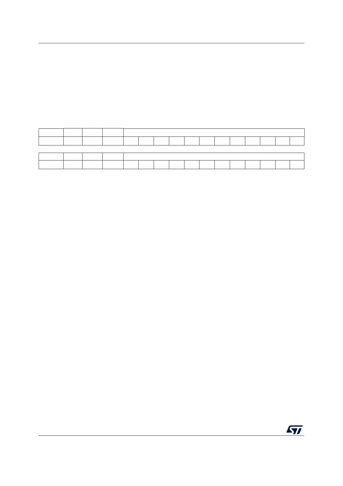
31 30 29 28 27 26 25 24 23 22 21 20 19 18 17 16
TEXTEN Res. Res. Res. TIMEOUTB[11:0]
rw rw rw rw rw rw rw rw rw rw rw rw rw
15 14 13 12 11109876543210
TIMOUTEN Res. Res. TIDLE TIMEOUTA[11:0]
rw rw rw rw rw rw rw rw rw rw rw rw rw rw
Bit 31 TEXTEN: Extended clock timeout enable
0: Extended clock timeout detection is disabled
1: Extended clock timeout detection is enabled. When a cumulative SCL stretch for more
than t
LOW:EXT
is done by the I2C interface, a timeout error is detected (TIMEOUT=1).
Bits 30:28 Reserved, must be kept at reset value.
Bits 27:16 TIMEOUTB[11:0]: Bus timeout B
This field is used to configure the cumulative clock extension timeout:
In master mode, the master cumulative clock low extend time (t
LOW:MEXT
) is detected
In slave mode, the slave cumulative clock low extend time (t
LOW:SEXT
) is detected
t
LOW:EXT
= (TIMEOUTB+1) x 2048 x t
I2CCLK
Note: These bits can be written only when TEXTEN=0.
Bit 15 TIMOUTEN: Clock timeout enable
0: SCL timeout detection is disabled
1: SCL timeout detection is enabled: when SCL is low for more than t
TIMEOUT
(TIDLE=0) or
high for more than t
IDLE
(TIDLE=1), a timeout error is detected (TIMEOUT=1).
Bits 14:13 Reserved, must be kept at reset value.
Bit 12 TIDLE: Idle clock timeout detection
0: TIMEOUTA is used to detect SCL low timeout
1: TIMEOUTA is used to detect both SCL and SDA high timeout (bus idle condition)
Note: This bit can be written only when TIMOUTEN=0.
Bits 11:0 TIMEOUTA[11:0]: Bus Timeout A
This field is used to configure:
The SCL low timeout condition t
TIMEOUT
when TIDLE=0
t
TIMEOUT
= (TIMEOUTA+1) x 2048 x t
I2CCLK
The bus idle condition (both SCL and SDA high) when TIDLE=1
t
IDLE
= (TIMEOUTA+1) x 4 x t
I2CCLK
Note: These bits can be written only when TIMOUTEN=0.

 Loading...