09/03
2-221
DC 3535/2240/1632, WC M24
10-125
Status Indicator RAPs
Initial issue
10-125 Duplex Wait Sensor On
Paper did not arrive at the Duplex Wait Sensor within the specified period of time.
Initial Actions
• Check condition and specification of the paper supply.
• Check the paper path for obstructions. Ensure that the Mylar Fingers in the Inverter Chute
Assembly are not bent or damaged.
• Check for wear and clean the Duplex Transport Roll.
• Check for wear and clean the Pinch Rolls.
Procedure
The jam associated with this fault is accompanied by a grinding or rattling sound from
the upper left rear.
YN
Enter dC330 [008-105] and press Start. Open the Duplex Module Cover and block and
unblock the Duplex Wait Sensor (PL 12.2). The display changes state.
YN
Press Stop. Check the circuit of the Duplex Wait Sensor (Figure 2). Refer to the OF
99-1 RAP for troubleshooting procedure.
Press Stop. Remove the Left Upper Cover (PL 2.7). Enter dC330 [008-056] and press
Start. The Duplex Transport Roll (PL 12.1) rotates.
YN
The Duplex Motor (PL 12.2) energizes.
YN
Press Stop. Refer to Figure 3. There is +24 VDC from pin A4 to pin A7 on
P626
YN
Go to the +24 VDC (Figure 4), and 24V RTN (Figure 1) Wirenets to trou-
bleshoot the missing voltage.
Refer to Figure 3. Check the 3 signal wires from the MCU PWB to P626 for
damage or open connections. If the wires are OK, Remove the Duplex Trans-
port Assembly (REP 8.3). Check the wiring from J626 to the Duplex PWB for
damage or open connections. If the wires are OK, replace the Duplex Motor
(PL 12.2). If the problem continues, replace the Duplex PWB (PL 12.2). If this
does not resolve the problem, replace the MCU PWB (PL 13.1).
Press Stop. Remove the Duplex Transport Assembly (REP 8.3). Check the Duplex
Motor and its associated pulleys and belts (PL 12.2) for damage, contamination and
misalignment.
Press Stop. Enter dC330 [008-042] and press Start. The Inverter Forward Clutch (PL
11.2) (CW) energizes.
YN
Press Stop. Check the circuit of the Inverter Forward Clutch (Figure 4). Refer to the
OF 99-4 RAP for troubleshooting procedure.
Press Stop. Enter dC330 [008-043] and press Start. The Inverter Reverse Clutch (PL
11.2) (CCW) energizes.
YN
Press Stop. Check the circuit of the Inverter Reverse Clutch (Figure 5). Refer to the
OF 99-4 RAP for troubleshooting procedure.
Press Stop.
• Ensure that the connectors shown in the circuit diagrams (Figure 2, Figure 3, Figure
4, Figure 5) are securely connected and that the wires are not damaged.
• Remove the Clutch Assembly and clean the Forward and Reverse Clutch (PL 11.2).
• If the problem persists, replace the MCU PWB (PL 13.1).
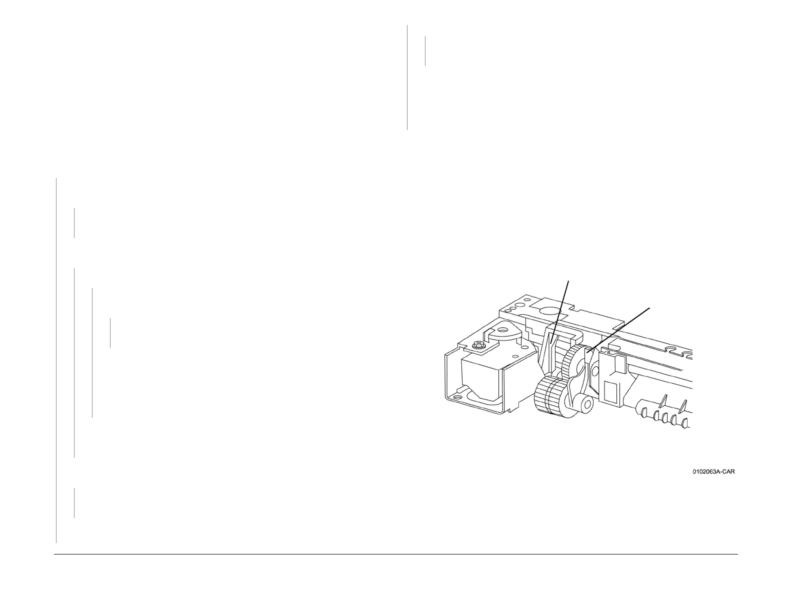
There is an alignment problem between the Inverter Transport (PL 11.1) and the Exit Transport
(PL 2.11). This can be caused by damage to the Rear Latch or the Reversing Gear Tab in the
Exit Transport (refer to Figure 1), or by damage to the Actuator on the Inverter Transport
(which engages the Reversing Gear Tab).
Examine the Exit Transport for damage to Rear Latch or the Reversing Gear Tab. Repair or
replace as required (PL 2.11).
If the Exit Transport appears to be OK, check the Inverter Transport for damage. Repair or
replace as required (PL 11.1).
NOTE: For DC 3535 and later DC 2240/1632 machines, the Interlock Actuator (PL 11.2) is a
separate piece. Alignment may be improved by removing the Actuator and placing a piece of
shim stock underneath it when reinstalling.
Figure 1 10-125 RAP Reversing Gear Detail
Reversing Gear Tab
Rear Latch
A
A
 Loading...


