09/03
2-239
DC 3535/2240/1632, WC M24
12-100
Status Indicator RAPs
Initial issue
12-100 H Transport Entrance Sensor On
The H Transport Entrance Sensor does not detect paper after the Registration Clutch (in IOT)
energized.
Initial Actions
• Check condition and specification of the paper supply.
• Check for obstructions in the paper feed path.
• Clean the H Transport Belt and check for wear.
• Check the Guides on the H Transport Cover for damage, wear or faulty installation.
Procedure
Enter dC330 [012-001] and press Start. The Finisher Drive Motor (PL 17.7) energizes (Fig-
ure 4).
YN
Remove the Rear Cover (PL 17.5). +24 VDC is measured between P/J879-2 and 3 on
the Finisher Drive Motor and GND.
YN
+24 VDC is measured between P/J846 - 5 and 7 on the Finisher PWB and GND.
YN
Replace the Finisher PWB (PL 17.13).
Check the wires from P/J846-5 and 7 to J879-2 and 3 for damage or poor contact.
Enter dC330 [012-001] and press Start. Less than +1 VDC is measured between P/
J879 -1 on the Finisher Drive Motor and GND.
YN
Replace the Finisher Drive Motor (PL 17.7).
Check wiring between P/J879 and P/J846 for damage or poor contact. If the check is OK,
replace the Finisher PWB (PL 17.13).
Press Stop. Enter dC330 [012-103] and press Start. Open the H Transport Cover (PL 17.3)
and actuate the H Transport Entrance Sensor (PL 17.4). (Figure 1) The display changes.
YN
Press Stop. Check the circuit of the H Transport Entrance Sensor (Figure 2). Refer to the
OF 99-2 RAP for troubleshooting procedure.
Close the H Transport Cover and press Stop. Enter dC330 [012-060 or 061] and press Start.
The Gate In Solenoid (PL 17.4) actuates (Figure 1).
YN
Press Stop. Check the circuit of the Gate In Solenoid. (Figure 3) Refer to the OF 99-4
RAP for troubleshooting procedure.
Press Stop.
• Ensure that the connectors shown in the circuit diagrams (Figure 2, Figure 3, Figure 4)
are securely connected and that the wires are not damaged.
• Check the H Transport and Finisher for a docking failure (PL 17.1).
• Check the Finisher Drive Motor and its associated gears and belts (PL 17.4, PL 17.7) for
damage, contamination or misalignment.
• Replace the H Transport Entrance Sensor (PL 17.4).
• If the problem persists, replace the Finisher PWB (PL 17.13) (Figure 5).
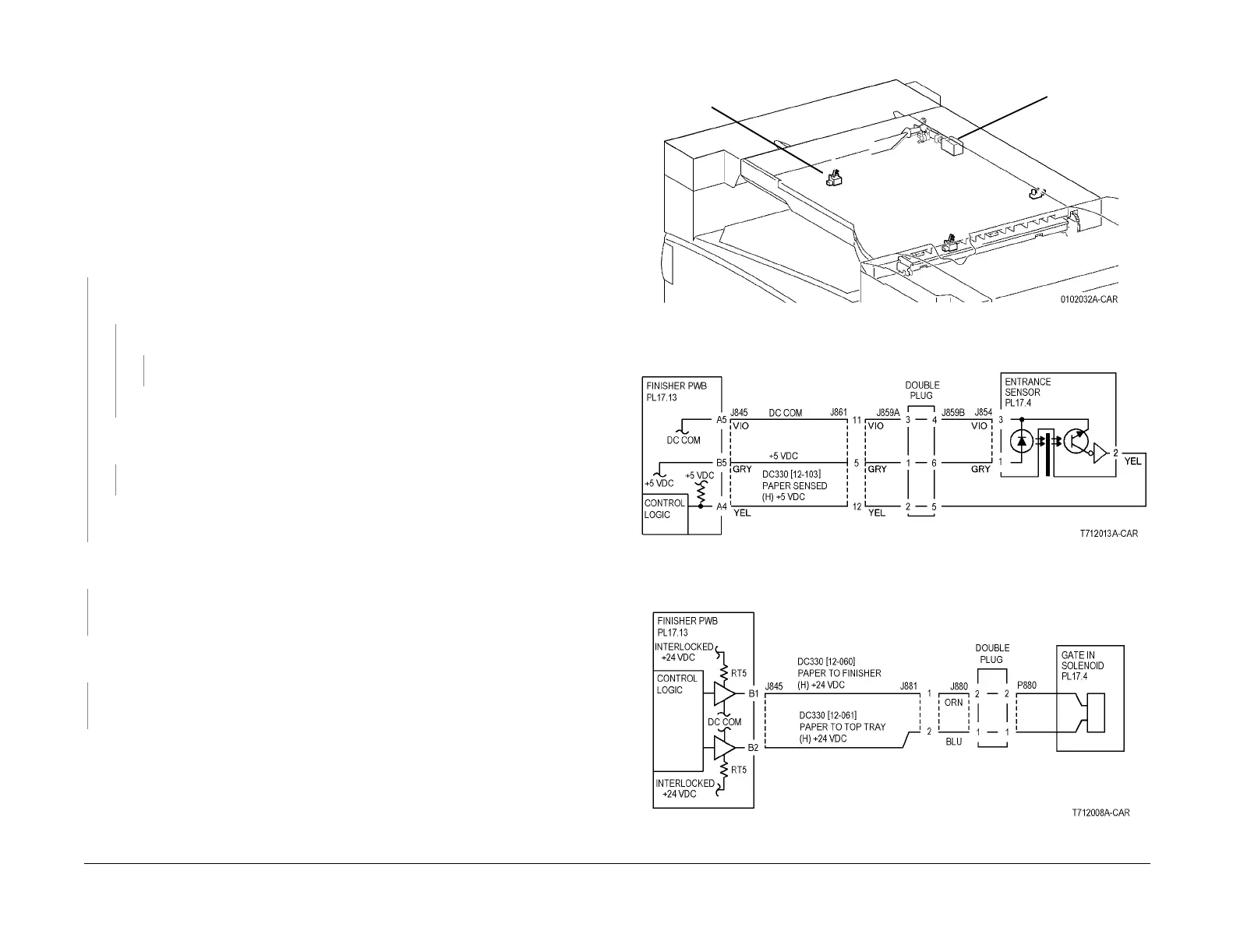
Figure 1 Component Location
Figure 2 12-100 RAP Circuit Diagram - H Transport Entrance Sensor
Figure 3 12-100 RAP Circuit Diagram - Gate In Solenoid
Entrance
Sensor
Gate In
Solenoid
 Loading...


