09/03
2-249
DC 3535/2240/1632, WC M24
12-170
Status Indicator RAPs
Initial issue
12-170 Set Eject
The Compiler Paper Sensor did not deactuate after the Eject Motor energized.
Initial Actions
• Check condition and specification of the paper supply.
• Check for obstructions in the paper feed path.
• Clean the Eject Roll and Eject Pinch Roll and check for wear.
Procedure
Enter dC330 [012-102] and press Start. Open the Top Cover (PL 17.6) and actuate the Com-
piler Paper Sensor (PL 17.10) (Figure 1). The display changes.
YN
Press Stop. Check the circuit of the Compiler Paper Sensor (Figure 2). Refer to the OF
99-2 RAP for troubleshooting procedure.
Press Stop. Enter dC330 [012-030] and press Start. The Eject Motor (PL 17.8) energizes
Figure 3).
YN
Remove the Rear Cover (PL 17.5). +24 VDC is measured between P/J881 -2 and 5 on
the Eject Motor and GND.
YN
+24 VDC is measured between P/J846- 6 and 12 on the Finisher PWB and
GND.
YN
Replace the Finisher PWB (PL 17.13).
Check wiring between P/J846- 6 and 12 and P/J881- 2 and 5 for damage or poor
contact.
+24 VDC is measured between P/J881- 1, 3, 4 and 6 on the Eject Motor and GND.
YN
Replace the Eject Motor (PL 17.8).
Check the wires from P/J846 to P/J881 for damage or poor contact. If the check is OK,
replace the Finisher PWB (PL 17.13).
Check the following:
• Ensure that the connectors shown in the circuit diagrams (Figure 2, Figure 3) are securely
connected and that the wires are not damaged.
• Check the Eject Motor and its associated gears, pulleys and belts (PL 17.8) for damage,
contamination or misalignment.
• Eject Clamp for an up and down movement failure (PL 17.8).
• Stacker Tray for foreign substance (PL 17.1).
• Replace the Compiler Paper Sensor (PL 17.10).
• If the problem persists, replace the Finisher PWB (PL 17.13) (Figure 4).
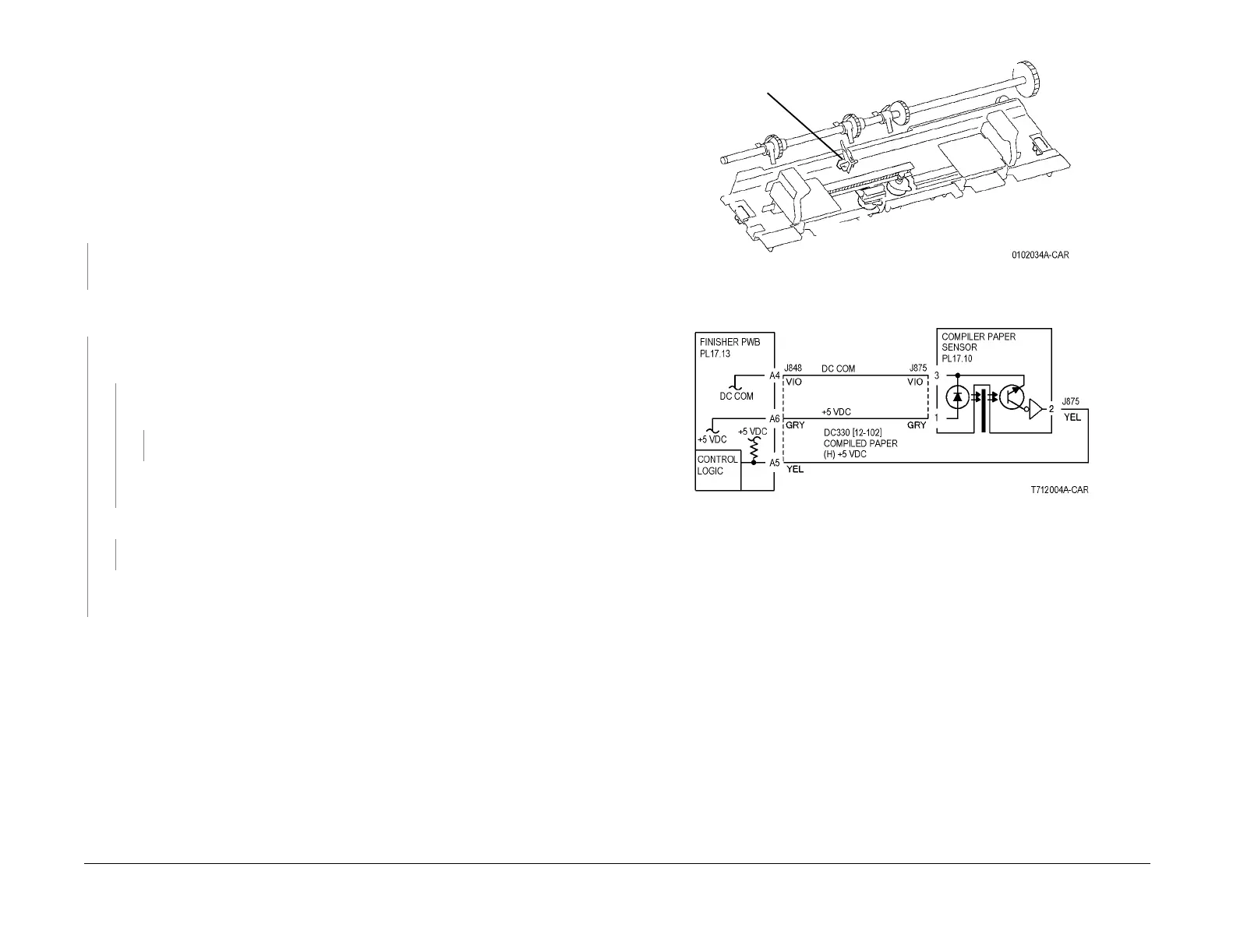
Figure 1 Component Location
Figure 2 12-170 RAP Circuit Diagram - Compiler Paper Sensor
Compiler
Paper
Sensor
 Loading...


