09/03
2-13
DC 3535/2240/1632, WC M24
1-300
Status Indicator RAPs
Initial issue
1-300 RAP
The Left Cover is open.
Procedure
Enter dC330 [001-301] and press the Start button. Open and close the Left Cover (PL 2.7).
The Display changes state.
YN
+24 VDC is measured between +24 LVPS P/J502-1 and GND(-).
YN
Replace the LVPS (PL 9.1).
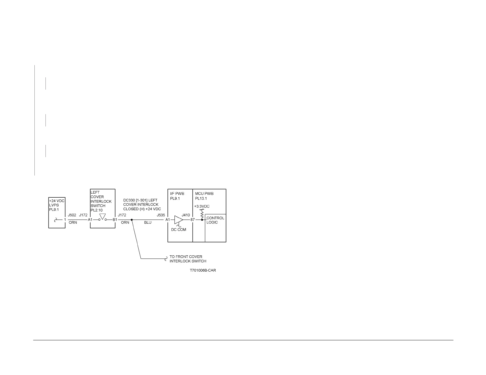
Disconnect P/J172 from the Left Cover Interlock Switch (PL 2.11). Refer to Figure 1 and
check the resistance between A1 and B1 when the switch is actuated. The resistance
is less than 3 ohms.
YN
Replace the Left Cover Interlock Switch (PL 2.11).
Reinstall the switch. Close the Left Cover (PL 2.7). +24 VDC is measured between P/
J535-A1 on the I/F PWB and GND.
YN
Repair the open circuit between the +24 VDC LVPS and the I/F PWB.
Replace the I/F PWB (PL 9.1).
If the problem continues, replace the MCU PWB (PL 13.1).
Check the installation of the Cover/Actuator.
Figure 1 1-300 RAP Circuit Diagram - Left Cover Interlock Switch

 Loading...


