09/03
2-17
DC 3535/2240/1632, WC M24
1-306
Status Indicator RAPs
Initial issue
1-306 RAP
The Duplex Cover is open.
Procedure
Enter dC330 [008-300] and press the Start button. Open the Duplex Transport. Actuate the
Duplex Cover Interlock Switch (PL 12.2) with a screwdriver. The Display changes state.
YN
Deactuate the Duplex Cover Interlock Switch. Approximately +3.3 VDC is measured
between the Drawer Connector P/J626-A6 (+) and GND (-).
YN
The machine is a DC 3535.
YN
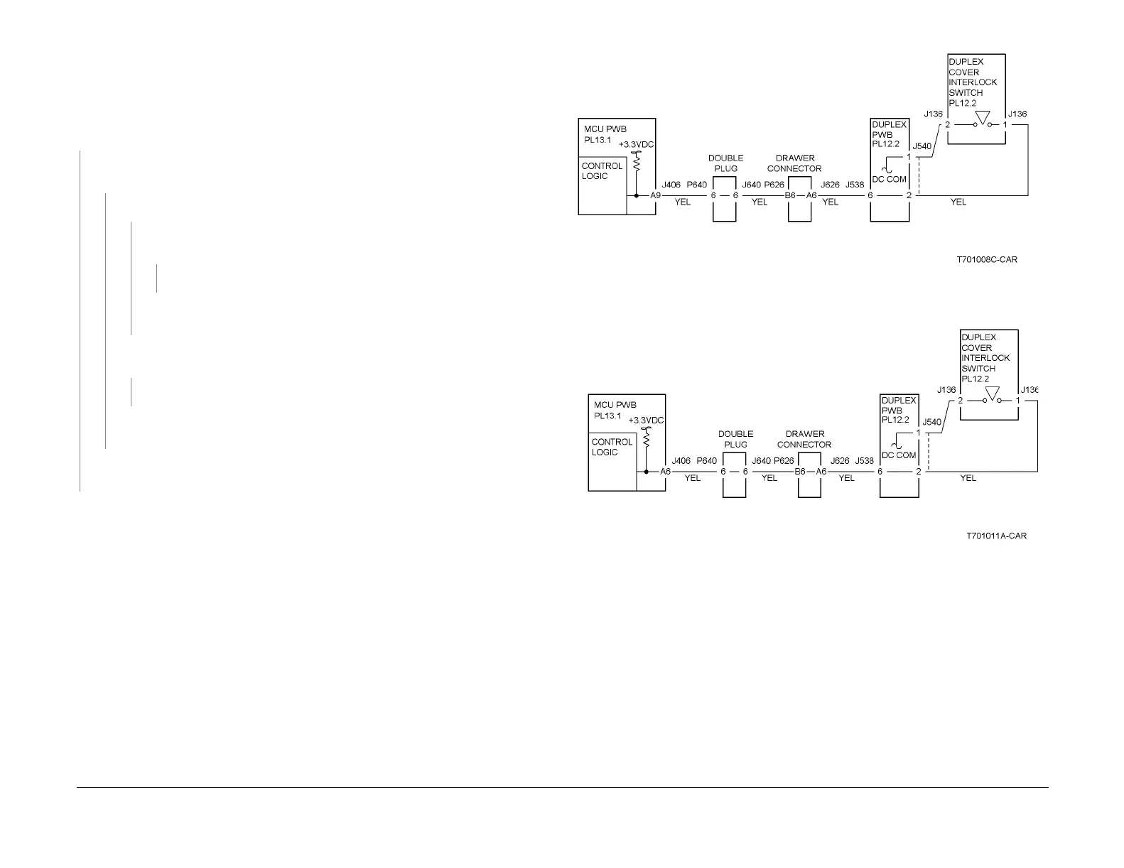
Refer to Figure 1. Approximately +3.3 VDC is measured between the MCU
PWB P/J406-A9 (+) and GND (-).
YN
Replace the MCU PWB (PL 13.1).
Repair the open circuit between the MCU PWB P/J406-A9 and Drawer Con-
nector between P/ J626-A6
Refer to Figure 2. Approximately +3.3 VDC is measured between the MCU PWB
P/J406-A6 (+) and GND (-).
YN
Replace the MCU PWB (PL 13.1).
Repair the open circuit between the MCU PWB P/J406-A6 and Drawer Connector
between P/ J626-A6
Check the wires at the Drawer Connector between P/ J626-A6 and the Duplex PWB P/
J540-1. If the wires are good, replace the Duplex Cover Interlock Switch (PL 12.2).
Check the Cover Actuator and the Cover installation. If there is no problem, replace the MCU
PWB (PL 13.1).
Figure 1 1-306 RAP Circuit Diagram - DC 2240/1632 Duplex Cover Interlock Switch
Figure 2 1-306 RAP Circuit Diagram - DC 3535 Duplex Cover Interlock Switch

 Loading...


