09/03
2-709
DC 3535/2240/1632, WC M24
OF 99-6, OF 99-7
Status Indicator RAPs
Initial issue
OF 99-6 2 Wire Motor Open
Procedure
NOTE: Before performing this RAP, ensure that the motor is free to rotate.
Enter dC330 [XXX-XXX].
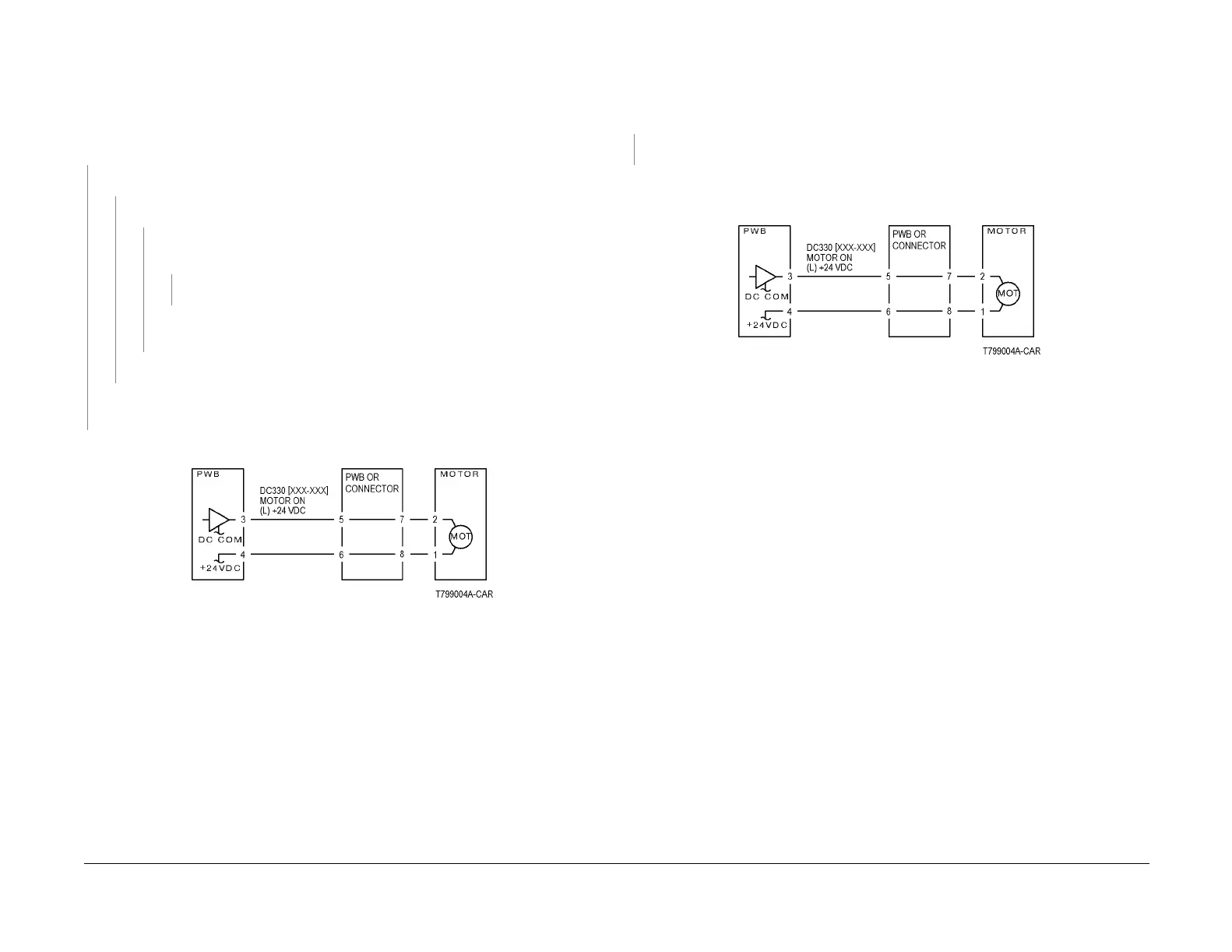
Refer to Figure 1. There is +24VDC measured between Pin 3(+) of the PWB and GND(-).
YN
There is +24VDC measured between the Motor Pin 2(+) of the Motor and GND(-).
YN
There is +24VDC measured between the Motor Pin 1(+) of the Motor and GND(-).
YN
There is +24VDC measured between the PWB Pin 4(+) of the PWB and GND(-
).
YN
Replace the PWB.
Check the wire between the PWB Pin 4 and the Motor Pin 1 for an open circuit
or poor contact.
Replace the motor.
Check the wire between the PWB Pin 3 and the Motor Pin 2 for an open circuit or poor
contact.
Replace the PWB.
Figure 1 OF 99-6 RAP Circuit Diagram - Motor
OF 99-7 2 Wire Motor On
Procedure
Turn off the power. Remove the PWB connector. Refer to Figure 1. There is 10 Ohm’s or
less measured between the connector Pin 3 and the frame.
YN
Replace the PWB.
Check the wire between the connector Pin 3 and the motor Pin 2 for a short circuit.
If the check is OK, replace the motor.
Figure 1 OF 99-7 RAP Circuit Diagram - Motor

 Loading...


