09/03
2-710
DC 3535/2240/1632, WC M24
OF 99-8
Initial issue
Status Indicator RAPs
OF 99-8 Set Gate Solenoid Open
Procedure
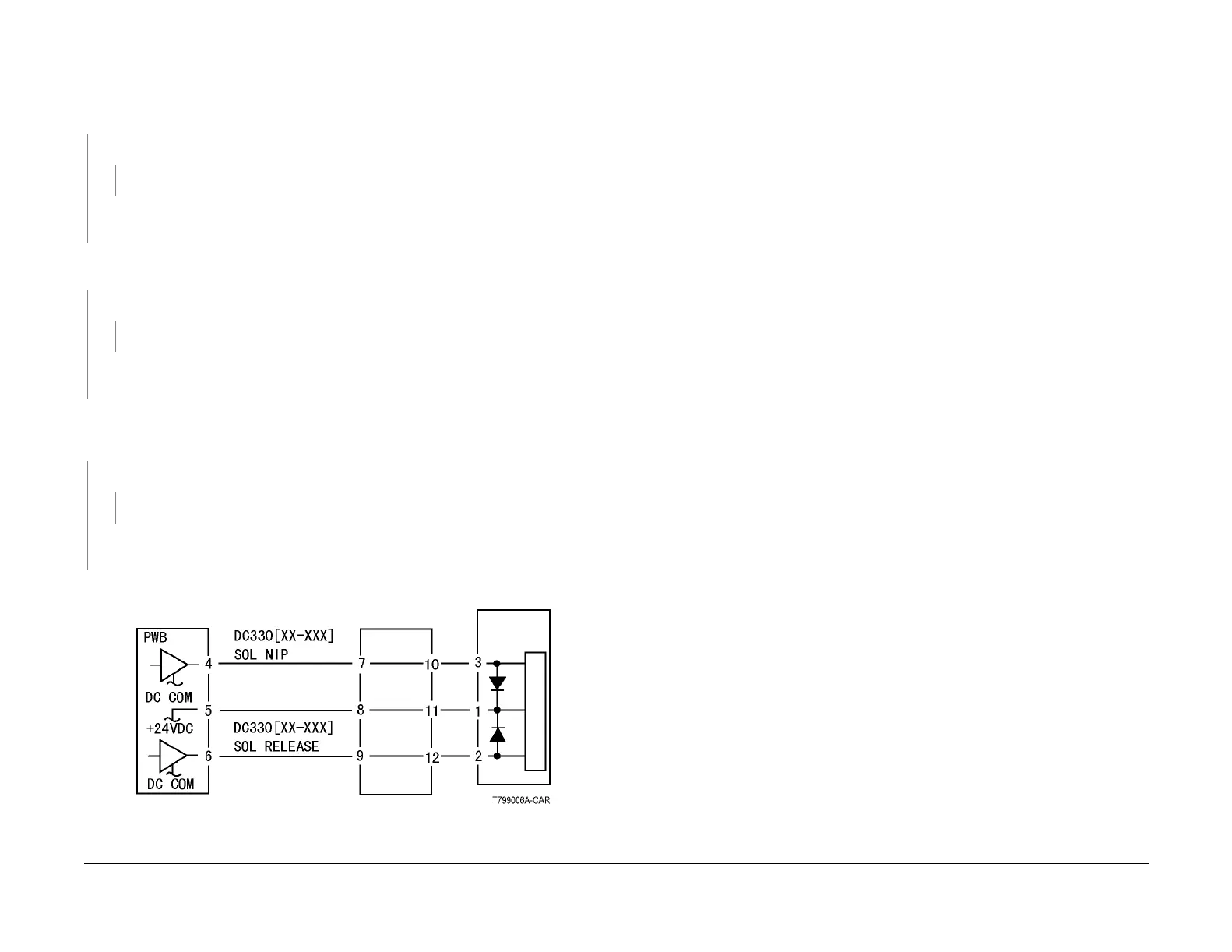
Refer to Figure 1. There is +24VDC measured between the Nip/Release Solenoid Pin 1 (+)
and GND (-).
YN
There is +24VDC measured between the PWB Pin 5 (+) and GND(-).
YN
Check +24VDC inputs on the PWB. If the check is OK, replace the PWB.
Check the wire between the PWB Pin 5 and the Nip/Release Solenoid Pin 1 for an open
circuit or poor contact.
Enter dC330 [XXX-XXX]. There is +24VDC measured between the PWB Pin 4 (+) and
GND(-).
YN
There is +24VDC measured between the Nip/Release Solenoid Pin 3 and GND
YN
Replace the Nip/Release Solenoid.
Check the wire between the PWB Pin 4 and the Nip/Release Solenoid Pin 3 for an open
circuit and poor contact.
Follow the following when the release caused a problem.
Go to the dC330 [XXX-XXX]. There is +24VDC measured between the PWB Pin 6 (+) and
GND(-).
YN
There is +24VDC measured between the Nip/Release Solenoid Pin 2 (+) and GND (-)
YN
Replace the Nip/Release Solenoid.
Check the wire between the PWB Pin 6 and the Nip/Release Solenoid Pin 2 for an open
circuit or poor contact.
Replace the PWB.
Figure 1 OF 99-8 RAP Circuit Diagram - Nip Solenoid

 Loading...


