09/03
6-109
DC 3535/2240/1632, WC M24
dC330
General Procedures and Information
Initial issue
004-011 Drum Motor YMC
(52mm/sec.)
Rotate at low speed. Remove all Drum Car-
tridges before energizing to prevent Belt
damage.
004-003
004-012 IBT Motor (52mm/
sec.)
Rotate at low speed. Operate with the IBT
Assy. removed to prevent Transfer Belt
damage.
004-002,
004-013
004-013 IBT Motor (high
speed)
Rotate at high speed. Operate with the IBT
unit removed. The Belt might be damaged
since the Belt Work Control is not per-
formed.
004-002,
004-012
004-014 IBT_5V ON ON = High. -
004-050 Fuser Fan, LV Fan
and Rear Fan
Rotation High
speed
Rotate the FUSER FAN, LV FAN and
REAR FAN at high speed. (Rotation is Low
at Power ON)
-
005-011 Set Gate Solenoid
Open
Turn Set Gate Open ON (Towards bottom
of Nudger Roll) for 5sec -> Auto OFF
-
005-012 Set Gate Solenoid
Close
Turn Set Gate Close ON (Towards bottom
of Nudger Roll) for 5sec -> Auto OFF
-
005-040 Feed Mot. DADF Feed Motor for 2sec -> Auto OFF -
005-055 Belt Motor Non
CVT Mode (CW)
Rotate the DADF Belt Motor forward. 005-056
005-056 Belt Motor Non
CVT Mode (CCW)
Rotate the DADF Belt Motor backward. 005-055
005-075 Regi Gate Solenoid Push the Regi Gate with the Arm to turn it
ON for 5sec -> Auto OFF
-
005-081 Exit Motor Non
CVT Mode
Operate the DADF Exit Motor -
005-083 Doc Ready switch ON the Doc Ready signal. -
005-084 Doc Set LED switch ON the DOC SET LED -
006-002 IIT Exposure Lamp switch the Lamp ON for 180sec -> Auto
OFF
-
006-004 IPS Cooling Fan
(Low speed)
After operating the IPS Cooling Fan at high
speed for 5sec, operate it at low speed. ON
= FAN. ON = 24V, FAN Slow: L->H (About
13V)
-
006-005 IIT Scan Motor
(Scan)
More it 50mm from current position in Scan
direction -> Auto OFF
006-006
006-006 IIT Scan Motor
(Return)
More it 50mm from current position in
Return direction -> Auto OFF
006-005
006-014 IPS Cooling Fan
(High speed)
Operate the IPS Cooling Fan at high
speed.
-
006-030 LD ON Enable Sig-
nal (concurrently
for 4 colors)
-
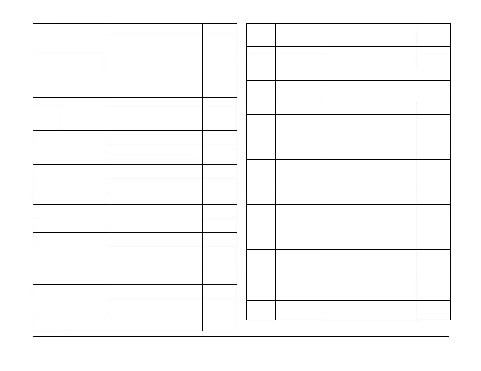
Table 2 Output Component Control Codes
Code Name Description Conflicts
006-031 Polygon Motor
Start Signal
-
006-032 SOS Gain Start-of-Scan Sensor gain signal
006-086 IIT Image Area IMG-AREA Signal Output. ON = P727
LVDS (Differential) High
-
006-091 Exchange To ADF Turn ON the document exchange com-
mand signal to the DADF
-
007-003 Tray 5 FEED
Clutch
-
007-004 HOTLINE_TRAY Not used. -
008-001 #1Feed Motor
(Fwd)
Feed (Rotate #1Feed Motor in paper feed
direction at 200mm/sec.)
8-002
008-002 #1Feed Motor
(Rev)
It switches OFF automatically 6sec after
LiftUp has started, or when the Level Snr
detected LiftUp. LiftUp cannot be per-
formed when the Level Snr should detect
LiftUp.
8-001
008-003 #2Feed Motor
(Fwd)
Feed (Turn #2Feed Motor On in paper feed
direction at 192mm/sec.)
8-004
008-004 #2Feed Motor
(Rev)
It switches OFF automatically 6sec after
LiftUp has started, or when the Level Snr
detected LiftUp. LiftUp cannot be per-
formed when the Level Snr should detect
LiftUp.
8-003
008-005 #3Feed Motor
(Fwd)
Feed (Turn #3Feed Motor On in paper feed
direction at 192mm/sec.)
008-006 #3Feed Motor
(Rev)
It switches OFF automatically 6sec after
LiftUp has started, or when the Level Snr
detected LiftUp. LiftUp cannot be per-
formed when the Level Snr should detect
LiftUp.
8-005
008-007 #4Feed Motor
(Fwd)
Feed (Turn #4Feed Motor On in paper feed
direction at 192mm/sec.)
8-008
008-008 #4Feed Motor
(Rev)
It switches OFF automatically 6sec after
LiftUp has started, or when the Level Snr
detected LiftUp. LiftUp cannot be per-
formed when the Level Snr should detect
LiftUp.
8-007
008-009 Dup Motor
(200.1mm/sec.)
Start operation. Switches OFF automati-
cally at 1000msec.
8-010, 011,
012, 053, 054,
055, 056
008-010 Dup Motor
(104mm/sec.)
Start operation. Switches OFF automati-
cally at 1000msec.
8-009, 011,
012, 053, 054,
055, 056
Table 2 Output Component Control Codes
Code Name Description Conflicts

 Loading...


