09/03
9-8
DC 3535/2240/1632, WC M24
Fax Kit Installation
Initial issue
Installation
Fax Kit Installation
Purpose
The purpose of this kit is install a Fax Module on WorkCentre 24 machines.
Kit Contents
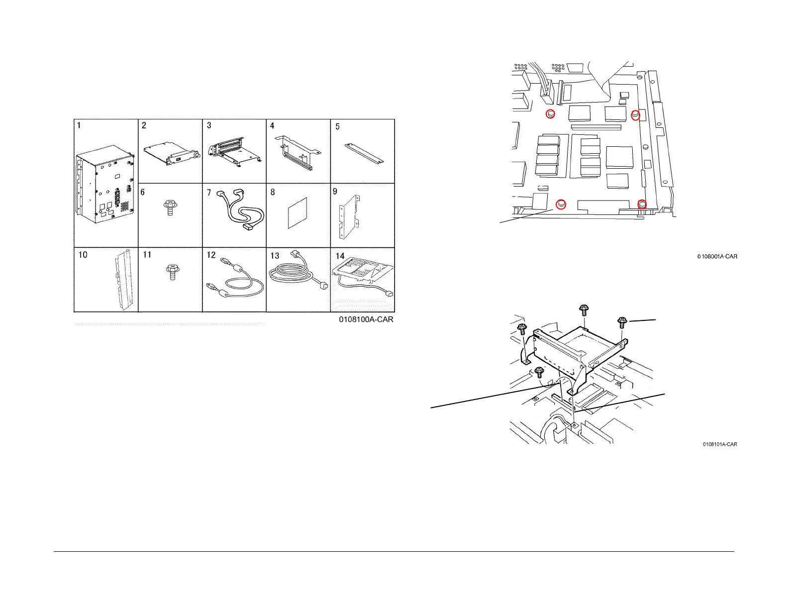
Check the kit contents against the following list:
Figure 1 Kit Contents
Procedure
Installing the Riser Chassis
1. Switch off the copier and disconnect both power cords.
2. Disconnect the Scanner Cable from the Rear Panel on the machine.
3. If applicable remove the Finisher from the machine (REP 12.4), including the Finisher
Gate Assembly (PL 17.2).
4. Remove the Rear Cover (REP 14.2).
5. Remove the Right Cover (REP 14.3).
6. Remove the Top Cover (REP 14.1).
CAUTION
Protect the Hard Drive Harness when removing the ESS Top Cover. The Hard Drive is
mounted to the cover. The harness remains connected to the ESS PWB while removing the
cover.
7. Remove the DIMM Cover and the ESS Top Cover (PL 13.1).
8. Remove the 4 screws shown in Figure 2.
Figure 2 Preparing to Install Riser
9. Install the Riser Chassis (Figure 3).
Figure 3 Installing Riser
10. Install the Guide Bracket and Plate (Figure 4).
Fax Module
Fax I/F PWB Riser Chassis
Guide Bracket
Plate
Screw, M3x6 (8)
Wire Harness
Label
Bracket (L)
Bracket (R)
Self-tapping
Screw, M3x6
One-
Touch Panel
Interface Cable
Phone Cable (2)
Rear of machine
Remove screws
(4).
1
Align the holes in the
Riser with the holes
in the ESS PWB.
2
Align the Riser connector
and ESS connector and
press firmly
3
Reinstall the screws
removed in step 8

 Loading...


