09/03
9-9
DC 3535/2240/1632, WC M24
Fax Kit Installation
Installation
Initial issue
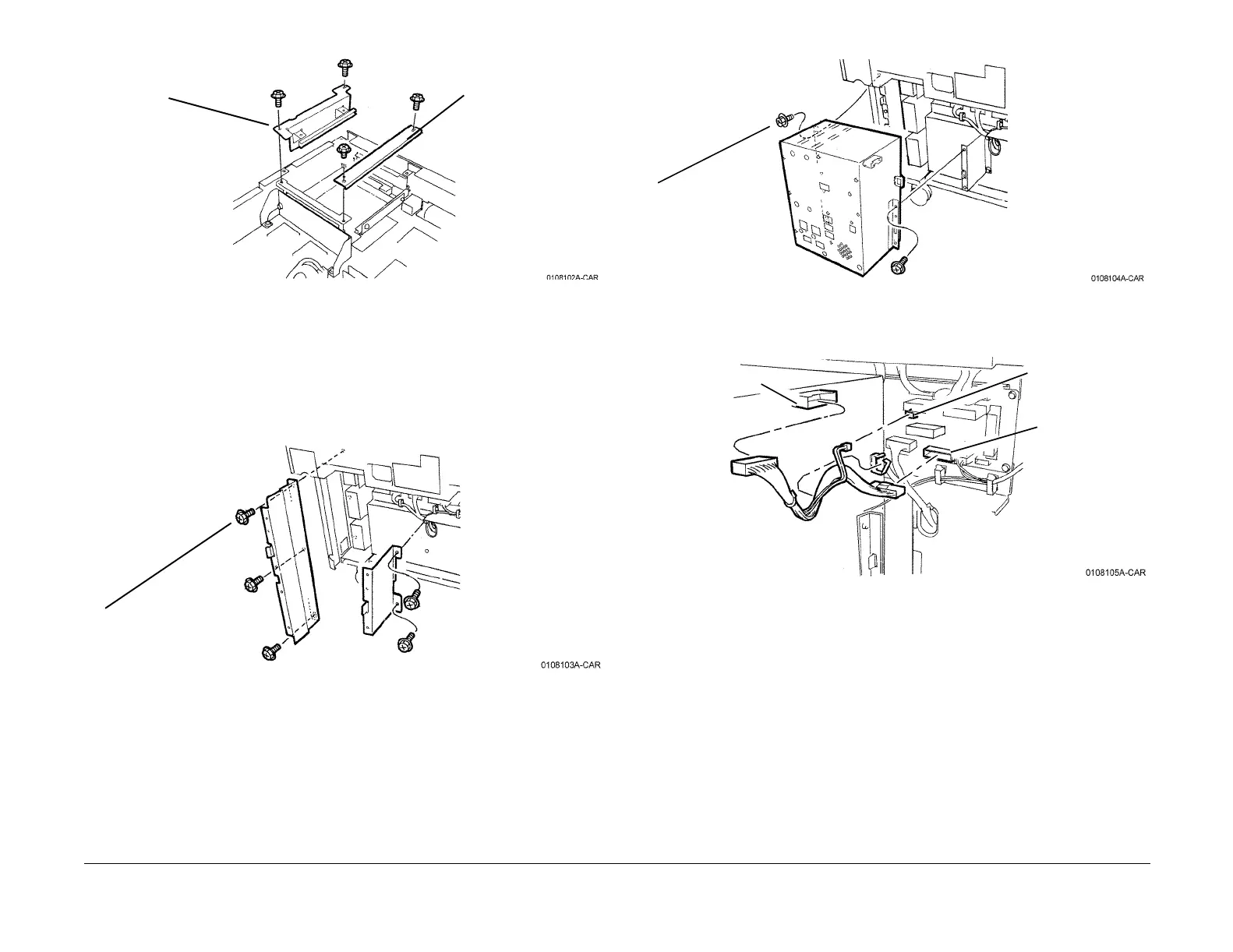
Figure 4 Installing Guide Bracket and Plate
11. Insert the Fax I/F PWB into the lower slot, ensuring the connectors mate correctly.
12. Tighten the thumbscrews on the front of the PWB.
13. Reinstall the ESS Top Cover and DIMM Cover (PL 13.1).
Installing the Fax Module
1. Remove the Tray Module Rear Cover (REP 14.9).
2. Install the Brackets (Figure 5).
Figure 5 Installing Brackets
3. Install the Fax Module (Figure 6).
Figure 6 Installing the Fax Module
4. Install the Wire Harness (Figure 7).
Figure 7 Installing Harness
5. Remove the Blind Covers on the Tray Module Rear Cover (Figure 8).
Guide Bracket
Rear of
machine
Plate
1
Install self-tapping
screws (5)
1
Install self-tapping
screws (6)
P351 on Fax Module
P564 on Tray
Module PWB
P561 on Tray
Module PWB
 Loading...


