Debug support (DBG) RM0367
958/1043 RM0367 Rev 7
33.3.3 Internal pull-up & pull-down on SWD pins
Once the SW I/O is released by the user software, the GPIO controller takes control of these
pins. The reset states of the GPIO control registers put the I/Os in the equivalent states:
• SWDIO: input pull-up
• SWCLK: input pull-down
Embedded pull-up and pull-down resistors remove the need to add external resistors.
33.4 ID codes and locking mechanism
There are several ID codes inside the MCU. ST strongly recommends the tool
manufacturers to lock their debugger using the MCU device ID located at address
0x40015800.
33.4.1 MCU device ID code
The STM32L0x3 products integrate an MCU ID code. This ID identifies the ST MCU part
number and the die revision.
This code is accessible by the software debug port (two pins) or by the user software.
Only the DEV_ID[15:0] should be used for identification by the debugger/programmer tools
(the revision ID must not be taken into account).
For code example, refer to A.20.1: DBG read device Id code example.
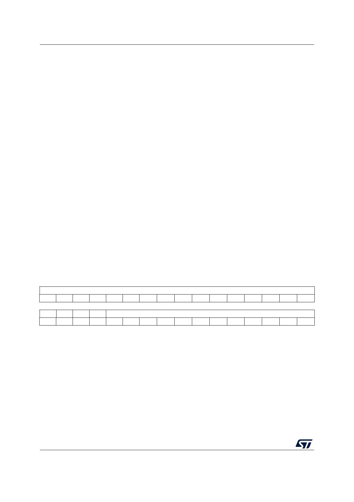
DBG_IDCODE
Address: 0x4001 5800
Only 32-bit access supported. Read-only
31 30 29 28 27 26 25 24 23 22 21 20 19 18 17 16
REV_ID
rrrrrr r r r r rrrrrr
1514131211109876543210
Res. Res. Res. Res. DEV_ID
rrrrrrrrrrr
Bits 31:16 REV_ID[15:0] Revision identifier
This field indicates the revision of the device (see Table 173: REV-ID values).
Bits 15:12 Reserved: read 0b0110.
Bits 11:0 DEV_ID[11:0]: Device identifier
This field indicates the device ID:
Category 3 devices: 0x417
Category 5 devices: 0x447

 Loading...