Annexes
R&S
®
ZNB/ZNBT
1544User Manual 1173.9163.02 ─ 62
Structure and syntax of the instrument messages are described in Chapter 7, "Com-
mand reference", on page 840. The chapter also provides a detailed description of all
messages implemented by the analyzer.
12.3.4 Handler I/O (universal interface)
Option R&S ZN-B14 / R&S ZNBT-Z14
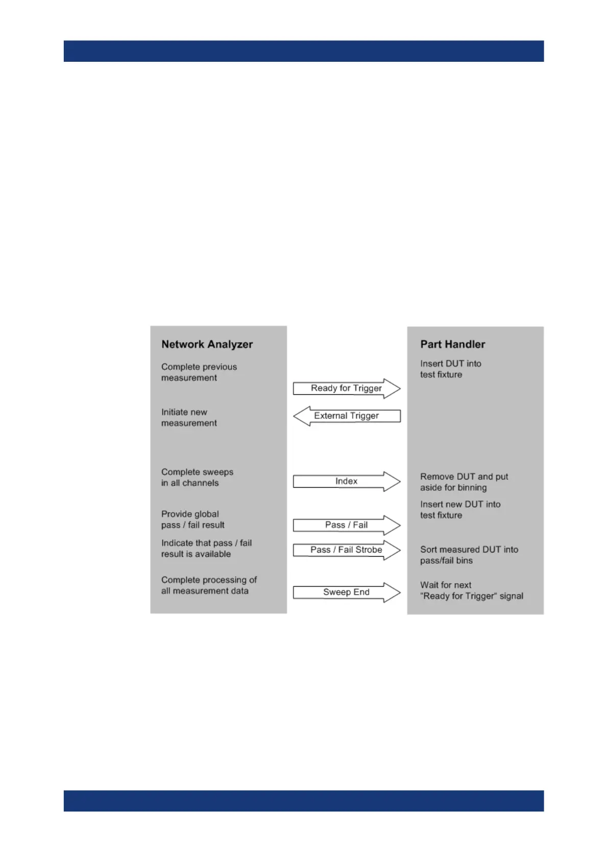
A network analyzer which is equipped with a Handler I/O (Universal Interface) option,
can interact with an external part handler. The digital control signals on the interface
connector indicate the possible start and the end of a measurement, as well as a
global limit check result. Typically, the handler will insert the device to be tested into a
test fixture, provide a trigger pulse to initiate the measurement, remove and replace the
device after the measurement is complete and sort it into pass/fail bins. A sample flow
diagram for this process is shown below.
Figure 12-1: Possible stages of an automated test
Preparation of the network analyzer and the part handler
The network analyzer configuration depends on the measurement to be made. Starting
from the preset state, you will usually have to adjust the following settings:
1. Enable external trigger:
Channel – [Trigger] > "Trigger" > "External"
Interfaces and connectors
 Loading...


