Concepts and features
R&S
®
ZNB/ZNBT
138User Manual 1173.9163.02 ─ 62
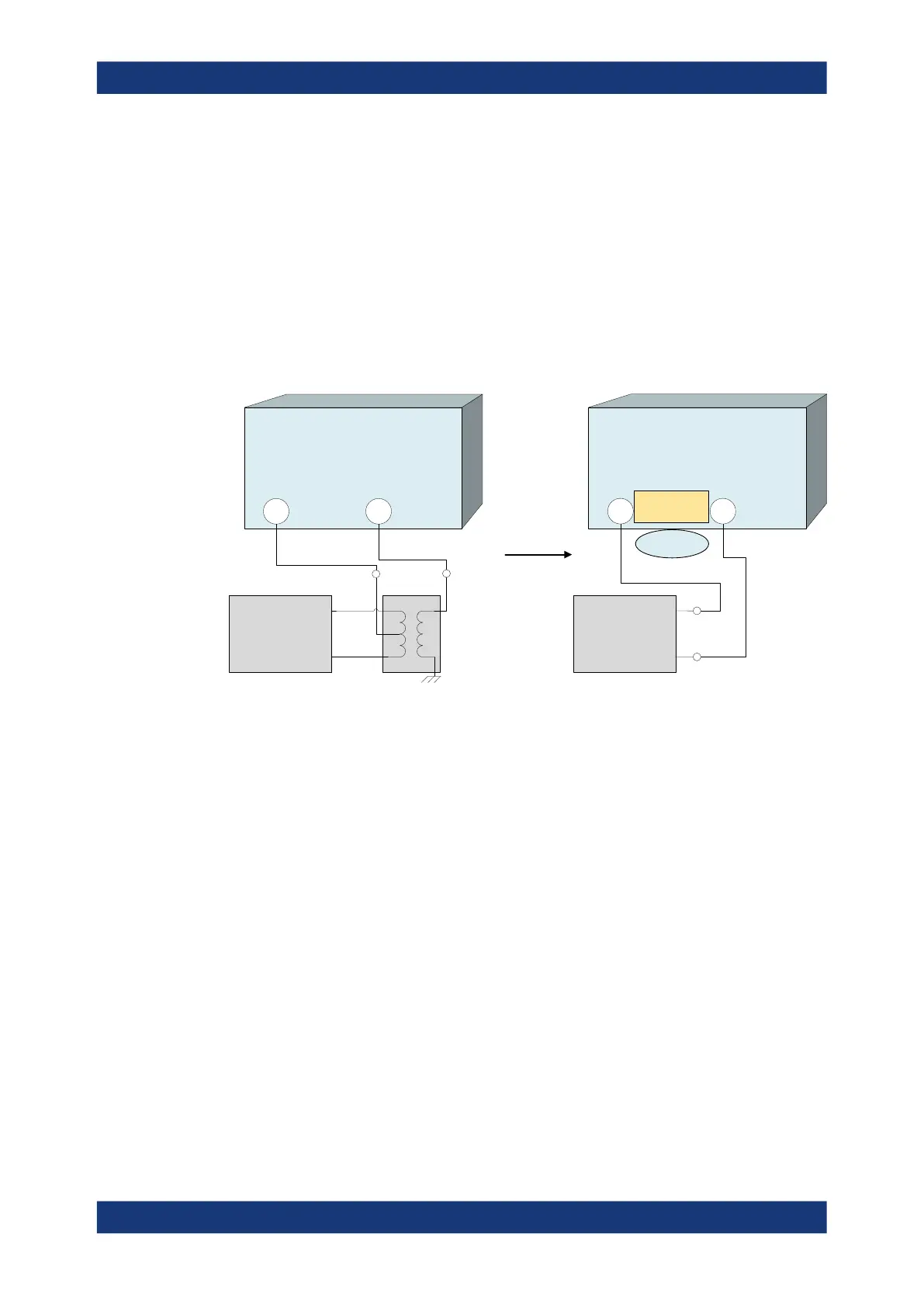
4.3.6 Unbalance-balance conversion
Unbalance-balance conversion is the simulation of one or more unbalance-balance
transformers (baluns) integrated in the measurement circuit. It converts the DUT ports
from an unbalanced state into a balanced state and virtually separates the differential
and common mode signals. The analyzer measures the unbalanced state but converts
the results and calculates mixed mode parameters, e.g. mixed mode S-parameters. No
physical transformer is needed.
To perform balanced measurements, a pair of physical analyzer ports is combined to
form a logical port. The balanced port of the DUT is directly connected to the analyzer
ports. For a two-port analyzer, a single balanced port can be defined.
VNA
1 2
Physical VNA ports
Common
mode
Differential
mode
Physical
transformer
(balun)
DUT
VNA
1 2
DUT
Balanced port
Internal balance-
unbalance
conversion
Logical
VNA ports
Unbalance-balance conversion avoids the disadvantages of real transformers:
●
There is no need to fabricate test fixtures with integrated baluns for each type of
DUT.
●
The measurement is not impaired by the non-ideal characteristics of the balun (e.g.
error tolerances, limited frequency range).
●
Calibration can be performed at the DUT's ports. If necessary (e.g. to compensate
for the effect of a test fixture), it is possible to shift the calibration plane using length
offset parameters.
●
Differential and common mode parameters can be evaluated with a single test
setup.
4.3.6.1 Balanced port configurations
Defining a balanced logical port requires two physical ports.
The physical ports (on the VNA and connected External switch matrices) are equiva-
lent and can be freely combined to balanced (logical) ports. Moreover, it is possible to
assign arbitrary, independent reference impedance values to each unbalanced port
and to the differential and common mode of each logical port.
Measurement results

 Loading...


