GUI reference
R&S
®
ZNB/ZNBT
584User Manual 1173.9163.02 ─ 62
●
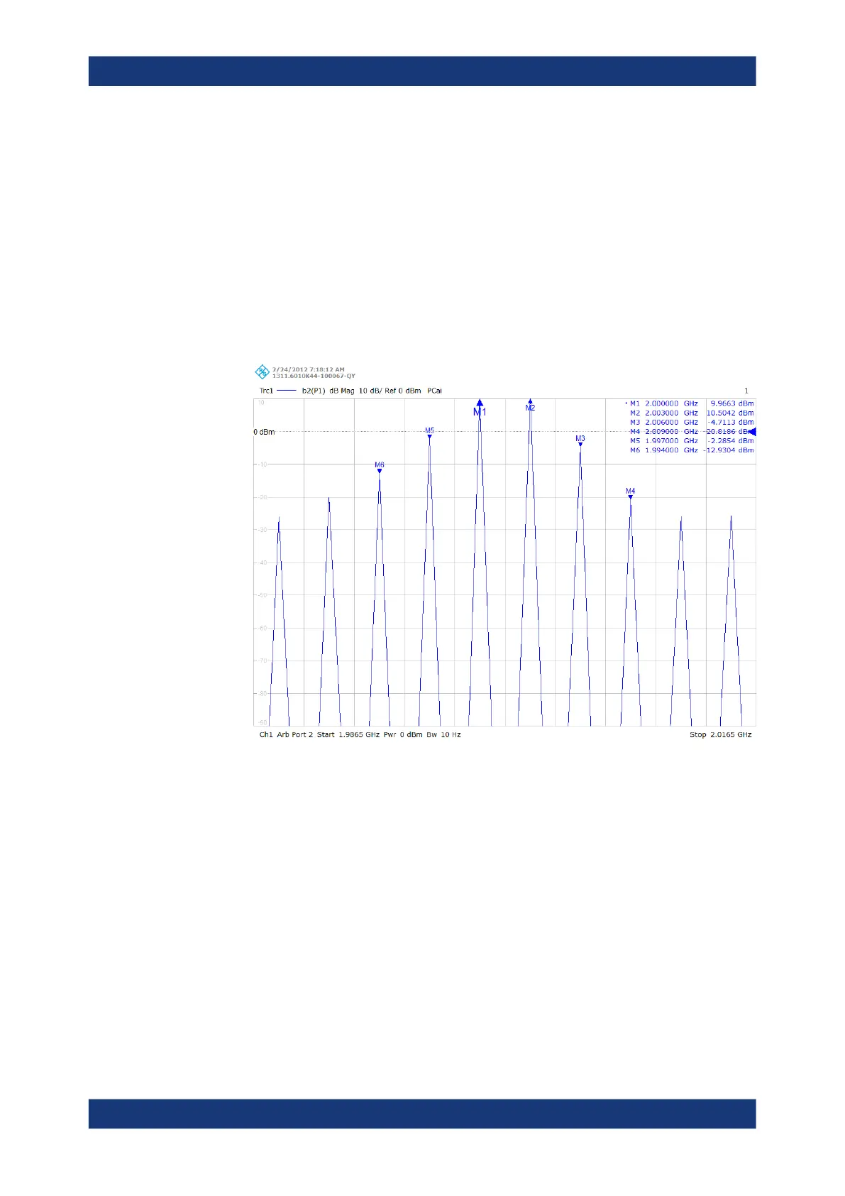
Max. IM Order: 9.
From left to right, the peaks correspond to the following intermodulation products:
– lower IM9
– lower IM7
– lower IM5 (marker M6)
– lower IM3 (marker M5)
– lower tone (marker M1)
– upper tone (marker M2)
– upper IM3 (marker M3)
– upper IM5 (marker M4)
– upper IM7
– upper IM9
●
"Add CW Mode"
Activates a new channel for the spectrum measurement. The "CW Frequency" plus
half the "Tone Distance" defines the center of the diagram.
●
"Max IM Order"
Defines the width of the spectrum measurement.
Remote command:
[SENSe<Ch>:]FREQuency[:CW]
[SENSe<Ch>:]FREQuency:IMODulation:SPECtrum:MORDer
[SENSe<Ch>:]FREQuency:IMODulation:SPECtrum[:STATe]
5.12.4.2 Intermodulation Presetting wizard
The "Intermodulation Presetting" wizard guides the user through the setup of an inter-
modulation measurement.
Channel Config softtool

 Loading...


